The environmental concerns and limited reserves of fossil fuels have generated an increased interest for alternative propulsive systems of vehicles. On the other hand, vehicle manufacturers are increasingly facing demands for reducing emissions of harmful gases by the vehicles in accordance with the increasingly stringent legislation.
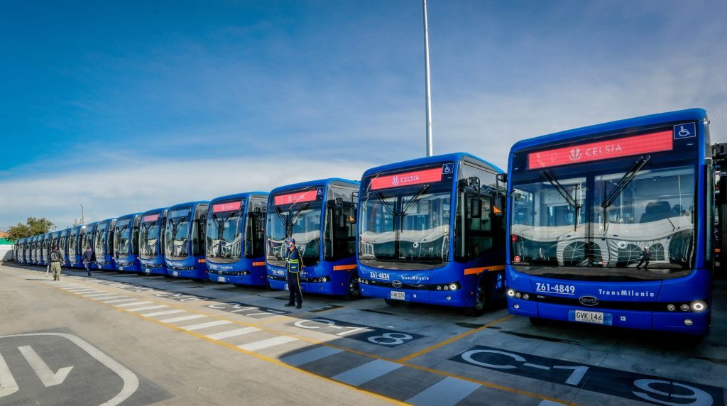
Buses as means of public transportation could reduce considerably the problems caused by the traffic in the urban areas through the usage, among other things, innovative techniques and technologies of vehicle propulsion systems.
The development of innovative technologies is increasingly oriented towards electrification of vehicle propulsion systems expected to lead to: a reduction of harmful emissions, an increased efficiency of vehicles, improved performances, a reduction of fuel consumption, a reduction of noise, and potentially lower maintenance costs. An electric drive technology implies a technology employing at least one drive device called electric motor. Three key electric drive technologies are: hybrid electric, battery electric, and fuel cell electric technologies.
In this chapter the application of electric technologies in the bus propulsion systems is considered through: an analysis of the state of development of city buses, an analysis of the advantages and shortcomings of electric drive technologies, and identification of the problems standing in the way of their greater commercialization. The presented examples of the developed city buses describe the basic characteristics of the applied propulsion systems and their advantages. The development of hybrid technologies for bus propulsion has grown considerably over the past several years. These technologies have reached massive applications in North America and their expansion to Europe has been initiated during the past several years.
In the part of the chapter dealing with hybrid electric buses a typical bus driving system and its components are reviewed and hybrid systems of the major world manufacturers are presented. Special attention is paid to the comparative analysis the hybrid electric buses and conventional and CNG buses. The available literature data have been critically processed and re-presented. Finally, the characteristics of hybrid city buses of some American and European manufacturers which have found the most widespread applications are reviewed.
The fuel cell powered buses draw special attention of users owing the efficiency of their propulsion system and their ability to cut drastically harmful emissions. Even though they are still not widely used, judging by the number of demonstrated projects the development of fuel cell buses is very intensive throughout the world. Barriers to their wider use are very high costs, lack of an adequate infrastructure, and relatively small radius of movement.
Fuel cell buses are vehicles with zero emissions. CO2 emissions depend on the type and method of production of fuel for fuel cells. In the part of the chapter dealing with fuel cell buses the typical bus configuration, its subsystems, its ecological characteristics, and costs are reviewed. Some of the development projects and characteristics of a new generation of fuel cell buses are presented.
Battery electric technologies are among technologies which reduce drastically the impact of a vehicle on the environment, however, they are still far from the proven technologies. The reason is the current level of developing technology of the energy storage devices for these vehicles. Influence of the batteries on commercialization of these buses is more pronounced compared to the other electric drive buses. A significant advancement in the area of energy sources has been made over the past several years by the development of lithium-ion batteries which lead to the development of an increased number of prototypes, even to a series production of these vehicles. In the part of the chapter dealing with battery electric buses the characteristics of some of these realized buses are reviewed.
In a separate part of this chapter the characteristics of energy storage device for the electric propulsion systems of the realized buses are presented, and the expectations from further development trends of the energy source devices are outlined.
An overview of electric drive technologies
Depending on the degree of electrification of propulsion system, Figure 1, three key electric drive technologies for power the electric vehicles are: hybrid electric, battery electric and fuel cell electric technologies [1].
Hybrid electric technology: A hybrid electric technology uses both an electric motor (EM) and an internal combustion engine (ICE) to propel the vehicle. Vehicles equipped with this technology are called Hybrid Electrics Vehicles (HEVs).
As can be seen from Figure 1, source of energy to power the vehicle with hybrid electric technologies are fuels, including alternative, which can be used in IC engines and electricity stored in the batteries or ultra capacitors. The charge energy storage to electricity is performed via IC engine and/or via the regenerative braking.
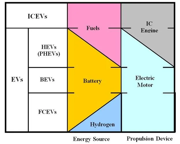
Special case of hybrid electric technology is plug-in hybrid electric (PHE) technology. It has a battery that can be charged off board by plugging into the grid and which enables it to travel certain kilometres solely on electricity. Vehicles equipped with this technology are called Plug-in Hybrid Electrics Vehicles (PHEVs).
Battery electric technology: Battery electric technology uses a relatively large on-board battery to propel the vehicle. Battery provides energy for propulsion through an electric traction motor(s) as well as power for all vehicle accessory systems. Some electric vehicles (EVs) can use to drive auxiliary devices like an on board generator, which makes them have characteristics of hybrid solutions. Vehicles equipped with this technology are called Battery Electrics Vehicles (BEVs).
Fuel cell electric technology: Fuel Cells are energy conversion devices set to replace combustion engines and compliment batteries in a number of applications. They convert the chemical energy contained in fuels, into electrical energy (electricity), with heat and water generated as by-products. Fuel cells continue to generate electricity for as long as a fuel is supplied, similar to traditional engines. However unlike engines, where fuels are burnt to convert chemical energy into kinetic energy, fuel cells convert fuels directly into electricity via an electrochemical process that does not require combustion. Vehicles equipped with this technology are called Fuel Cell Electrics Vehicles (FCEVs).
Electric drive technologies also, usually, incorporate other technologies, which reduce energy consumption, for example regenerative braking. That allows the electric motor to re-capture the energy expended during braking that would normally be lost. This improves energy efficiency and reduces wear on the brakes.
Electric drive technology configurations
Hybrid electric drive configurations consist of a fuel-burning prime power source – generally an ICE–coupled with an electrochemical or electrostatic energy storage device. These two power sources work in conjunction to provide energy for propulsion through an electric traction drive system. Power for all vehicle accessory systems can be provided electrically or mechanically from the ICE or combinations of both. There are currently many different hybrid-electric system designs utilizing ICE, alternative fuels engines, gas turbines or fuel cells in conjunction with batteries. These design options are grouped in three categories: series, parallel and series-parallel configurations.
A series hybrid-electric drive system, Figure 2, consists of an engine directly connected to an electric generator (or alternator). The arrows indicate the mechanical and electrical energy flow.
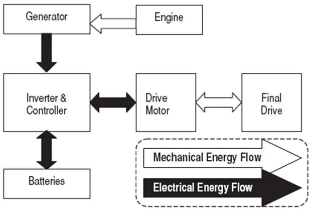
Power from the generator is sent to the drive motor and/or energy storage batteries according to their needs. There is no mechanical coupling between the engine and drive wheels, so the engine can run at a constant and efficient rate, even as the vehicle changes speed. The serial hybrid technology is the most common hybrid technology.
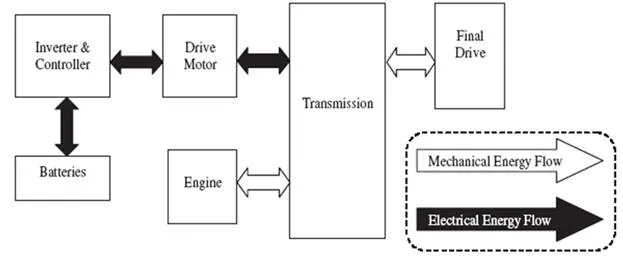
In a parallel hybrid-electric drive system, Figure 3, both of the power sources (engine and electric motor) are coupled mechanically to the vehicle’s wheels. In different configurations, the motor may be coupled to the wheels either through the transmission (pre-transmission parallel design) or directly to the wheels after the transmission (post-transmission parallel design). Each of these configurations has its advantages.
A series-parallel design, also known as power-split or dual mode hybrid system, is interesting because with proper control strategy it can be designed to take advantage of both parallel and series types and avoid their drawbacks.
Battery electric drive system are illustrated in Figure 4. The two types of system configurations are possible depending on the positioning and size of the electric motors.
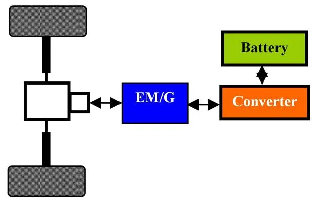
The central motor type is currently more common. However, the requirement to transfer power from the motor to the wheels does involve some losses in efficiency through friction.
The hub motor type can avoid many of the transmission losses experienced in the central motor type, but are a less regularly used technology.
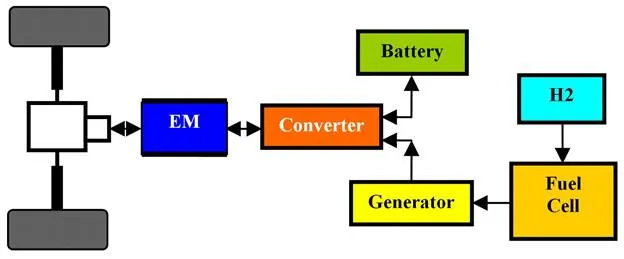
In fuel cell drive system fuel cell is providing the electric energy needed to run of vehicles. There are two types of fuel cell drive configuration:
- Fuel cell drive without energy storage device (non-hybrid fuel cell vehicles) and
- Fuel cell drive with energy storage device (hybrid fuel cell vehicles), Figure 5.
Fuel cell hybrids operate much like other hybrid electric vehicles but with fuel cells producing electricity that charges the batteries, and a motor that converts electricity from the batteries into mechanical energy that drives the wheels.
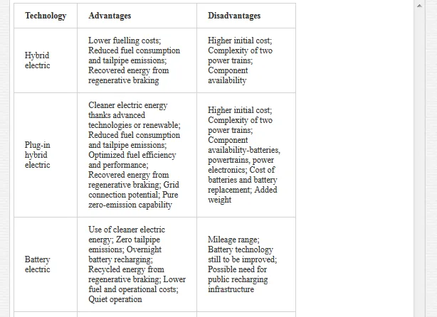
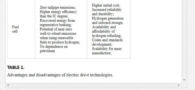
Advantages and disadvantages of electric drive technologies
There are some major advantages of electric drive technologies but there are also some disadvantages. Table 1 summarizes the advantages and disadvantages of a hybrid-electric, plug-in hybrid electric battery and fuel cell drive systems [2]:
Hybrid Electric Buses
At the IAA 1969 in Frankfurt, Daimler presented the first electric test bus–an early example of hybrid drive technology. In 1979, Daimler has launched a five-year model trial with a total of 13 Mercedes-Benz OE 305 electric-diesel hybrid buses in regular service. Since 2008 Orion hybrid buses are in regular service on the roads of major U.S. cities, but from 2009 Mercedes-Benz Citaro BlueTec Hybrid is in daily operation [3].
The first sales of serial hybrid city buses in Japan began 1991, when Hino delivered test buses in eight cities.
From 1997 until today leaders by the number of hybrid buses in commercial use are the United States and Canada.
Hybrid electric bus architectures
A hybrid electric bus (HEB) usually combines an internal combustion engine with the battery and an electric motor. The ICE can be fueled by gasoline, diesel, or other (natural gas, biofuel) and work either in series or in parallel with the electric motor. Regenerative braking capability in HEBs minimizes energy losses by recovering some of the kinetic energy used to slow down or stop a vehicle.
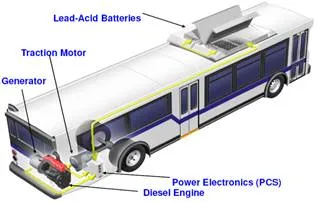
In a series hybrid configuration [4], Figure 6, the ICE drives a generator to feed the electric motor and recharge the battery. Braking energy can be captured and stored in the battery (“regenerative braking”). The engine can be downsized compared to a conventional drive-train with the same performance, meaning lower ICE weight and higher energy efficiency.
The electric motor powers the drive system, using either energy stored in batteries, or from the engine, or from both as needed. The engine is more efficient at lower speeds and higher load, so the series hybrid is preferred for slow and start-and-stop city driving.
In a parallel hybrid configuration both the engine and the electric motor are linked to the transmission so that either of them, or both at the same time, may provide the power to turn the wheels. Since the parallel hybrid configuration allows the engine to drive the wheels also through a direct mechanical path, it offers better efficiency than a series hybrid configuration, and a more functional and flexible design.
Hybrid Electric Bus Components
The principal hybrid-electric bus components include:
- an Auxiliary Power Unit (APU),
- a drive motor,
- a controller and inverter,
- an energy storage device and
- other auxiliary systems, such as air conditioning and lighting.
Auxiliary Power Units: Auxiliary Power Units (APUs) used in hybrid-electric buses are available in a number of configurations including IC engines, fuel cells, and with different fuels, such as diesel, gasoline and compressed natural gas (CNG), liquid natural gas (LNG) and propane. The engine is typically sized for the average bus power demand, not peak power demand since the energy storage device provides supplementary power. Engines in hybrid configurations also operate over a narrower range of load and speed combinations compared to engines in conventional buses.
Drive motors: Two primary types of electric motors can be used in electric vehicles, direct current (DC) motors and alternating current (AC) motors. On a power comparative basis, an AC motor generally exhibits higher efficiency, has a favourable power to size/weight ratio, is less expensive and generates regenerative braking energy more efficiently than a DC motor. Electric drive motors are connected to the vehicle wheels either directly, referred to as wheel motors, or through a transmission and differential assembly. Wheel motors are more efficient both in drive cycle and in the regenerative cycle by eliminating the losses in the mechanical transmission and the differential. However, wheel motors are expensive.
Controller and inverter: The electronic controller regulates the amount of energy, (DC power in the case of batteries), that is transferred or converted to AC power by the inverter (in AC motors) for acceleration. It also ensures that voltage is maintained within the specifications required for operating the motor. An electronic controller can also recover electrical energy by switching the motor to a generator in order to capture the vehicle’s kinetic energy via regenerative braking. The controller also ensures that the regenerative current does not overcharge a battery.
Energy storage devices: Energy storage devices provide necessary of the energy in hybrid-electric buses to supplement the APU energy when there is a high demand (e.g., acceleration from stop, speed acceleration, climbing an up-hill gradient) and to recover and store the energy generated during deceleration (e.g., braking, down-hill coasting).
Major manufacturers of hybrid systems
The major manufacturers of hybrid systems are shown in Table 2:
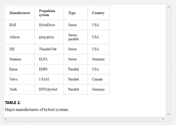
BAE Systems is a major integrator and supplier of integrated hybrid electric propulsion for Orion hybrid electric buses manufactured by Daimler Buses North America. BAE Systems produces the HybriDrive series propulsion system. The HybriDrive is composed of a traction motor and a traction generator to provide power to the vehicle. The liquid cooled, high power-to-weight ratio electric traction motor connects directly to a standard drive shaft and rear axle to provide traction power and regenerative braking. HybriDrive series system powers more than 3.500 buses [5].
Allison has developed EP50 parallel hybrid electric propulsion system with two motors capable of producing 75 kW of continuous power and up to 150 kW of power at full potential. Although designed as a parallel architecture, a power-split or two-mode hybrid electric bus can operate in either a series, or a parallel configuration. There are more than 4,600 buses with the Allison Two Mode Parallel Hybrid Systems in operation across 216 cities and 9 countries. The buses have driven more than 600 million kilometres, saved over 75 million litres of fuel and eliminated more than 197.000 metric tones of CO2 [6].
ISE Corporation produces the ThunderVolt series drive system who has five key subsystems: Motive Drive Subsystem (electric drive motors, motor controller, gear reduction system, and related components); Auxiliary Power Unit Subsystem (engine, electric generator, and related components); Energy Storage Subsystem (integrated pack of either batteries or ultracapacitors); Vehicle Control and Diagnostics and Electrically-Driven Accessories (electrical power steering and braking systems, air conditioning systems, and related components). ISE components for electric and hybrid drive are manufactured by Siemens (ELFA). ThunderVolt packs have been integrated in over 300 in-service buses, and operated for over 10 million miles (16,09 million km) cumulative [7].
Siemens ELFA hybrid propulsion system was initially developed in the mid 90’s for diesel electric buses. To date, Siemens has outfitted more than 700 hybrid busses in the U.S., Italy, Germany and Japan. More than 6 Million operation hours attest to the reliability of the system [8] Rugged liquid-cooled induction motors with power ratings from 50 kW to 180 kW with reduction gearboxes are used as standard for ELFA traction systems. Permanent-magnet generators are used for all of the latest ELFA traction drive generation. The traction converters play a key role in ELFA traction systems. The complete ELFA traction system is controlled using just one standard traction converter software.
Eaton hybrid power system (EHPS) uses a parallel configuration [9]. EHPS consists of an automated clutch, electric motor/generator, motor controller/inverter, energy storage unit, automated manual transmission and an integrated supervisory hybrid control module, takes energy created during braking and regenerates it for later use. An electric motor/generator is located between the output of an automatic clutch and the input to an automated mechanical transmission. The electric motor’s peak output is 44 kW.
Volvo has developed a parallel hybrid system [10] with integrated starter alternator motor (ISAM) system that can be used across the complete product range. ISAM is located between the diesel engine and the gearbox and facilitates a compact parallel hybrid package. ISAM integrates the starter motor, electric motor, generator and electronic control unit into one component. The electric motor is used to start and accelerate the bus up to about 20 km/h, while the diesel engine takes over at higher speeds.
Voith presented its parallel DIWAhybrid system at the American Public Transportation Association (APTA) show in 2008. DIWAhybrid system builds on the proven DIWA automatic transmission and is designed for up to 290 kW power input and a maximum input torque of 1.600 Nm. At 150 kW electric traction power, the DIWAhybrid system reduces the load of the diesel engine enough for the latter to be substantially smaller than on conventional diesel buses [11]. Voith has begun production of DIWAhybrid drive system for city buses in the USA at the end of 2011.
Hybrid electric bus characteristics
An advantage of a hybrid-electric bus over a conventional bus is theoretically better fuel economy and lower exhaust emissions.
Capital, maintenance and operation cost: Hybrid buses can cost up to $500.000, a significant increase over a standard diesel city bus, the cost of which is closer to $300.000 [12]. The major cost associated with hybrid buses is battery replacement, as batteries today are not expected to last the 12-year life of a city bus.
Fuel and maintenance (operating) cost savings over the life of the bus are expected to help recover the higher initial (capital) cost. Specifically, operating cost savings are expected through the following features: increased fuel economy; extended brake life; no transmission to service; less moving parts; less engine wear and less expensive engine.
Emissions and fuel economy: With regard to emissions, clearly hybrids are not providing the zero emission. Nevertheless, some testing on hybrid buses has demonstrated that hybrids offer emissions benefits that are comparable to or better than clean diesel and CNG buses. There are four primary sources of efficiency and emissions reduction found in HEBs [13]: smaller engine size, regenerative braking, power-on-demand, and constant engine speeds and power output.
By adding an electric motor a hybrid electric bus can be equipped with a smaller, more efficient combustion engine.
Regenerative braking recovers energy normally lost as heat during braking, and stores it in the batteries for later use by the electric motor.
Another feature that saves energy and reduces emissions in HEBs is the ability to temporarily shut off the combustion engine during idle or coasting modes.
In a hybrid application, the bus can be designed to use its diesel engine only at the engine’s optimum power output and engine speed range.
Barriers to widespread application: The hybrid vehicles are still a “work-in-progress”. Many studies noted that hybrid buses still require improvements in three technology areas: energy storage, electrically-driven accessories and on-board diagnostics.
Comparative analysis between the different buses
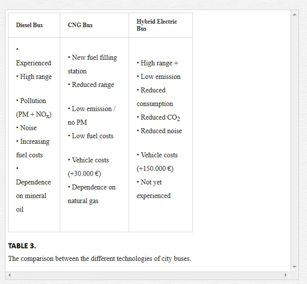
An overall comparison of buses with different technologies (diesel, CNG and hybrid electric) have been realized in the COMPRO project and the results are presented in the report “Cost /effectiveness analysis of the selected technologies” [14]. A comparison of buses is based on several parameters, technological, financial, environmental and planning-based, such as reliability, eployment flexibility, fuel price, range, exhaust gas emissions, noise, extra infrastructual needs. The considerations made above are summarized in Table 3. Advantages of each compared technology are featured in green, disadvantages in red.
Another comparison is based on a West Virginia University’s (WVU) study of city bus life cycle cost (LCC) [15, 16]. It covers the folowing bus types: diesel buses using ultra low sulfur diesel (ULSD), compressed natural gas (CNG) buses, and hybrid electric buses. LCC factors included capital costs (bus procurement, infrastructure, and emissions equipment) and operation costs (fuel, propulsion-related system maintenance, facility maintenance, and battery replacement) available from the literature.
A bus 12-year life cycle cost (LCC) analysis for a fleet of size of 100 buses was performed based on information available in the literature, manufacturers’ specifications, and fuel economy data gathered by WVU [15, 16]. Only technology-dependent factors relevant to bus propulsion were considered; driver and management cost were excluded. Buses were assumed to operate at a national average speed of 12.7 mph (20.48 km/h), to travel for 32.007 mile (about 51.500 km) per year, and to seat 40 passengers for the purposes of calculation.
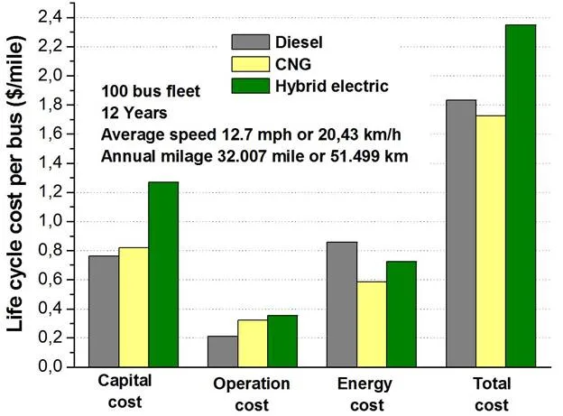
Capital costs for vehicle procurement includes refueling station (CNG bus), depot modification, and emissions reduction equipment (diesel bus). Infrastructure costs for CNG bus technology include two costs: for depot modification and for refueling stations. Operational costs include compression electricity (CNG bus), facility maintenance, propulsion-related system maintenance, battery replacement (hybrid bus), and fuel consumption. Warranty was not considered. Fuel costs were calculated from the product of national annual average mileage, estimated fuel economy, and predicted fuel price. All prices were in 2008 dollars and CNG price data were all converted to the base of diesel (energy) equivalent.
Figure 7 representing total LCC was created for the capital and operation costs (without fuel consumption), and energy cost, per bus per mile.
The capital cost hybrid buses was slightly higher than CNG and diesel buses. However, operation cost analysis was similar for all bus types. Although hybrid buses offered the best fuel economy, this was offset by the battery replacement cost. Generally, the LCC total cost showed that diesel buses are still the most economic technology.
The West Virginia University’s report [15] presents estimates for 2007 city bus regulated and greenhouse gas emissions. Tailpipe emissions (particulate matter (PM), nitrogen oxides (NOx) and greenhouse gas (CO2)) and fuel economy estimations were based on recent emissions and fuel economy studies, and adjusted with best engineering approach.
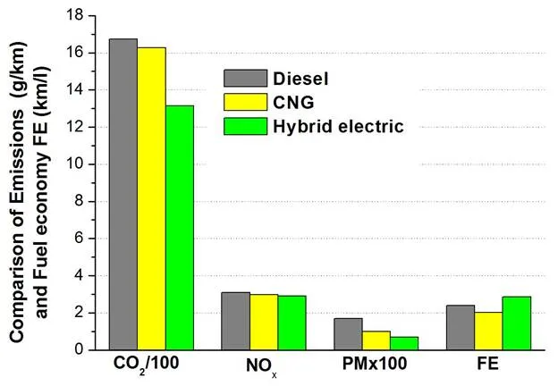
For simpler presentation of emissions and fuel economy by the three typical bus fleets (diesel, CNG and hybrid buses), the results given in the WVU study are appropriately processed and presented in Figure 8 [17]. Comparative values in Figure 8 represent average values for three typical driving cycles (MAN, OCTA, and CBD cycles). As can be seen from Figure 8 hybrid buses were attractive in offering emissions advantages. The estimation showed that hybrid buses offered lower tailpipe CO2, NOx and PM than the diesel and CNG buses. Figure 8 shows that the diesel hybrid bus fuel economy is better than the diesel bus fuel economy about 19%.
Hybrid electric bus solutions
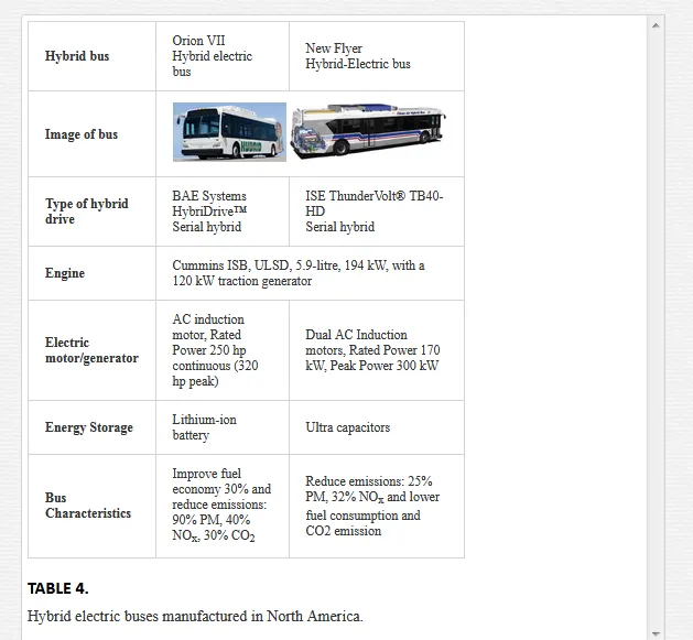
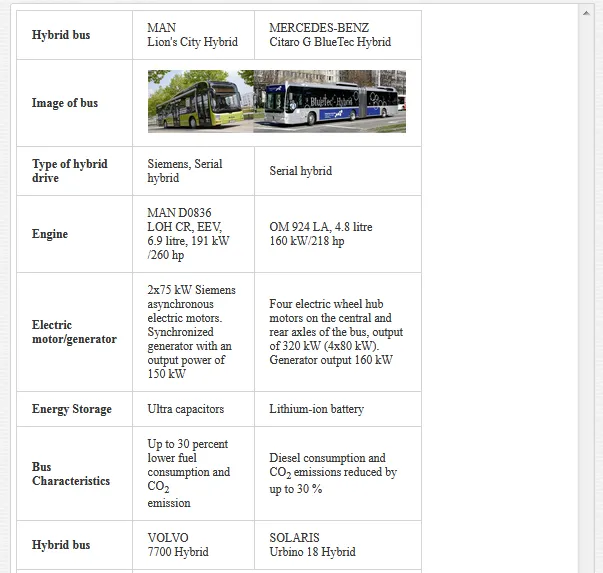
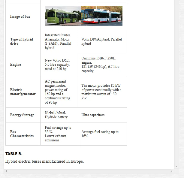
The use of hybrid technology has become a popular issue in recent years. Hybrid solutions are principally available for all main propulsion types, thus with Diesel, CNG, fuel cells etc. Table 4 [18, 19] and Table 5 [20] show some typical hybrid electric bus solutions of major bus manufacturers with IC engine.
Besides the mentioned, other manufacturers of hybrid buses are: Gillig, ISE Corporation (North America); Scania, Irisbus Iveco, Van Hool, VDL Bus & Coach, Hess AG (Europe); Tata Motors, Toyota-Hino, Hyundai Motor Company, Mitsubishi Fuso (Asia).
Fuel cell buses
Fuel cells for bus applications have generated an enormous amount of attention over the last several years, as they offer the promise of a clean, efficient transportation system no longer dependent on fossil fuels. The fuel cell has a life expectancy about one-half that of an internal combustion engine. Thus, consumers would have to replace the fuel cell twice in order to achieve a vehicle operating lifetime equivalent to that of a traditional engine.
Fuel cell buses (FCBs) require a substantial new infrastructure, support, and training requirements will depend on what type of fuel is used for the fuel cells. Most demonstrations and available buses use pure hydrogen stored in compressed gas form.
Fuel cell bus configurations
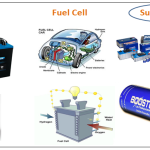
All fuel cell vehicle concepts use electric motors to power the wheels, typically accomplished through the combination of an electric battery storage system and an on-board hydrogen fuel cell. Depending on the degree of hybridization, the battery may provide pure “plug-in” electricity to drive the vehicle some distance. The battery system would be complemented by a hydrogen storage system and a fuel cell, with the goal of extending the driving range to 300 miles (483 km). Early fuel cell bus designs involved an electric drive train, where a fuel cell generates electricity which is directly supplied to an electric motor. A new generation of FCBs is based on the hybrid concept. Figure 9 shows typical arrangement of the components in FCB [21]. Key system components are: fuel cell system, energy storage system, hydrogen storage system, wheel drive, cooling system, and auxiliaries.
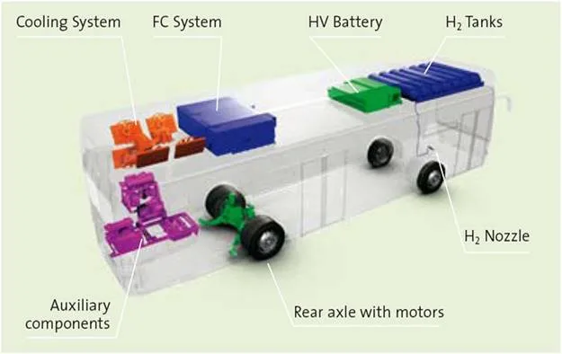
Fuel cell system: A fuel cell is an energy conversion technology that allows the energy stored in hydrogen to be converted back into electrical energy for end use. In a fuel cell vehicle, an electric drive system, which consists of a traction inverter, electric motor and transaxle, converts the electricity generated by the fuel cell system to traction power to move a bus. The fuel cell system and additional aggregates are usually located on top of the roof of the bus.
Fuel cells are classified by their electrolyte and operational characteristics. For application in vehicles mostly used are the Polymer Electrolyte Membrane (PEM) fuel cells. They are lightweight and have a low operating temperature. PEM fuel cells operate on hydrogen and oxygen from air.
Alkaline fuel cells (AFCs) are made by one of the most mature fuel cell technologies. AFCs have a combined electricity and heat efficiency of 60 percent efficient.
A newer cell technology is the Direct Methanol Fuel Cell (DMFC). The DMFC uses pure methanol mixed with steam. Liquid methanol has a higher energy density than hydrogen, and the existing infrastructure for transport and supply can be utilized.
There are some major fuel cell manufacturers supplying fuel cell power plants for heavy-duty applications: Ballard Power Systems and Hydrogenics (Canada), United Technologies Corporation (UTC) Fuel Cells, Enova Systems (USA), Shanghai Shen-Li High Tech Co. Ltd. (China), Siemens and Proton Motor Fuel Cell GmbH, (Germany), Toyota (Japan), Hyundai Motor Co. (South Korea).
Energy storage system: Energy storage systems are generally based on battery packs and/or ultracapacitors (generally up to 100 kW). Maximum power output and storage capacity vary depending on hybrid architecture. Lithium-ion battery technology is the most appropriate of energy storage technology for use in the buses. The batteries are usually located on top of the roof of the bus. FCBs are equipped with regenerative braking.
Hydrogen storage system: Gaseous hydrogen serves as the fuel. It is stored in compressed gas tanks, the number of which is decisive for the maximum range but also confines passenger capacity. The hydrogen storage system has been downsized as a result of the improved efficiency of the drive train. This has led to the reduction in the overall weight of the bus. The cylinders to storage hydrogen on board operate at an increased pressure of 350 bars.
Wheel drive: The electric motor can be either a single main motor or hub–mounted (where the motor is designed within the wheel). The bus may be equipped with a central traction system which will be located at the left hand side in the rear of the bus. The rear axle has 2 wheel hub motors and has been specifically developed to match the required speeds, load capabilities and energy efficiency. It also serves as a generator for energy regeneration during braking.
Cooling system: While running hydrogen through a fuel cell, water is of course being produced. Some of it becomes steam and leaves the system quite easily, as seen at the steam vent at the back of the bus. Yet, because PEM cells are sensitive to high heat the cell stacks must be cooled down. Therefore the byproduct from producing the electricity will always partially turn into liquid water that can accumulate in the stack and slow down the process. This can happen during idle times or at full speed. Therefore all PEM cells need a mechanism that clears the stacks once in a while or else the electricity production will be slowed down. The majority of the stack manufacturers use liquid cooled systems, with radiators to dissipate heat.
Auxiliaries: The auxiliary components in the FCB may be driven electrically. This means that they operate only on demand and are not driven continuously. This solution is typical for FCBs, which are based on the hybrid concept. This will result in a higher efficiency and lower maintenance of the components.
Fuel cell bus characteristics
Fuel cells offer a number of potential benefits that make them appealing for transport use such as greater efficiency, quiet and smooth operation, and, if pure hydrogen is used on board the bus, zero emissions in operation and extended brake life. Infrastructure, buses, fuel, and maintenance costs associated with hydrogen fuel cells are currently prohibitively expensive. The cost of facilities has ranged from several hundred thousand dollars up to $4,4 million for a maintenance facility, fueling station, and bus wash [22]. Currently, fuel cells for buses are not a commercial product. The existing fuel cell buses are prototypes, manufactured in fairly small numbers. Fuel cell buses can cost $1 to $3 million (or more) since they are hand-built prototypes utilizing a pre-commercial technology.
The hydrogen fuel itself is also currently very expensive. Costs range depending on the method of hydrogen production. One of the major constraints for use of the fuel cell buses is the refueling time for hydrogen buses. Filling over 30kg of hydrogen in less than 5 minutes is not currently feasible without pre-cooling the hydrogen (as the temperature increase at these high fill rates would damage the hydrogen tanks) [23].
Some comparisons with different bus technologies (diesel, hybrid diesel-hybrid and fuel cell), in terms of CO2 emissions per km traveled, have shown significant benefits of FCBs [23]. CO2 emissions of fuel cell buses ranging from 0 to 1,8 kg/km. Zero emissions are related to renewable hydrogen and electricity. Emissions of diesel hybrid buses are 0,69 to 1,2 kg/km, but emission of diesel buses are 1,05 to 1,5 kg/km.
Fuel cell bus projects
The introduction of new types of buses in urban public transport is sometimes a challenging process that includes testing, demonstration and limited production with a tendency to increase the number of vehicles. Fuel cell-powered buses continue to be demonstrated in public transport service at various locations around the world. Many demonstration projects have been launched in the last 10 years in various stages of implementation. Many have been completed, and some of them are still active. An overview of mainly fuel cell city bus development projects is given below [21]:
The HyFLEET:CUTE project has involved the operation of 47 hydrogen powered buses in regular public transport service in 10 cities on three continents. The Project started in 2006 and concluded at the end of 2009. HyFLEET:CUTE was co-funded by the European Commission and 31 Industry partners through the Commission’s 6th Framework Programme.
ECTOS (Ecological City Transport System) was an initiative to test three Citaro fuel cell buses in Reykjavik, Iceland. The project was financially supported by the European Commission. The project started at mid-2003 and now the buses are decommissioned.
STEP (Sustainable Transport Energy Project) is a project to explore the use of alternative transport energies in Perth, Australia. It includes the operation three Citaro fuel cell buses. It is funded by the government of Western Australia with support from the Australian government. The project started at mid-2004 and now the buses are decommissioned.
CHIC (Clean Hydrogen In European Cities) is the active project which involves integrating 26 FC buses in daily public transport operations and bus routes in five locations across Europe – Aargau (Switzerland), Bolzano/Bozen (Italy), London (UK), Milan (Italy), and Oslo (Norway). The CHIC project is supported by the European Union and has 25 partners from across Europe, which includes industrial partners for vehicle supply and refueling infrastructure. The project will guide additional regions in Europe in their first fleet application of fuel cell hybrid buses in public transport from 2012 onwards [24]. The buses in the CHIC project will be supplied by three different manufacturers – Mercedes-Benz (Germany), Van Hool (Belgium) and Wrightbus (UK).
“NaBuZ demo” (Sustainable Bus System of the Future – Demonstration) is German-funded project [25] in which the Hamburger Hochbahn AG produced four Mercedes-Benz Citaro FuelCELL Hybrid buses. Since 2011, the first Citaro FuelCELL Hybrid bus is involved into service.
The National Renewable Energy Laboratory (NREL) has recently published a status report documenting progress and accomplishments from demonstrations of fuel cell city buses in the United States. The report describes the status and challenges of fuel cell propulsion for transport and summarizes the introduction of fuel cell city buses in North America. Three major programs are [26]:
- Federal Transit Administration’s (FTA) National Fuel Cell Bus Program (NFCBP) includes developing the 11 new buses, expanding the fuel cell manufacturers beyond Ballard and UTC Power to include Hydrogenics and Nuvera, and exploring multiple bus sizes and hybrid propulsion designs.
- Zero Emission Bay Area (ZEBA) Group Demonstration includes 12 next-generation fuel cell city buses with redesigned Van Hool chassis, the newest UTC Power fuel cell power system, and fully integrated hybrid propulsion system.
- BC Transit Fuel Cell Bus Demonstration includes 20 fuel cell buses in Whistler, Canada. The buses are from New Flyer, use Ballard fuel cells, and have hybrid propulsion from ISE/Siemens.
Other projects: In China more than 50 FCBs were used during the Asian Games in 2010 and the Olympics Games in 2008. In Japan, Toyota-Hino has launched several dozen fuel cell buses in the period since 2003. In Korea, a Hyundai fuel cell bus has operated since 2006 [27].
New generation of fuel cell buses
Mercedes-Benz fuel cell hybrid buses: Mercedes-Benz has promoted the use of fuel-cell hybrid buses around the world over the past nine years. Since 2003, a total of 36 Mercedes-Benz Citaro buses equipped with second-generation fuel cells were driven a combined total of more than 2,2 million kilometres in a total of approximately 140.000 hours of operation [28].
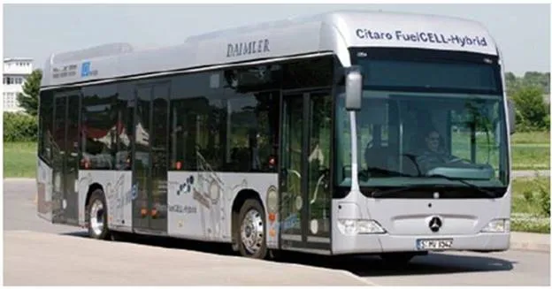
Production of the second generation of Mercedes fuel-cell hybrid buses started in November 2010 under the CHIC project. Compared with the fuel cell buses which were tested in Hamburg in 2003, the new Citaro FuelCELL Hybrid, Figure 10, provides several significant new features [25]: hybridization with energy recovery and storage in lithium-ion batteries, powerful electric motors with 120 kW of continuous output in the wheel hubs, electrified power take-off units and further enhanced fuel cells. These should achieve an extended service life of at least six years or 12.000 operating hours.
New additions are the lithium-ion batteries which for example store recovered energy. With the power stored there the new Citaro FuelCELL Hybrid can drive several kilometres on battery operation alone. In general, the design of the new FuelCELL buses is largely the same as that of the Mercedes-Benz BlueTec Hybrid buses that run in regular service; these buses also get electrical energy from a diesel generator. Thanks to improved fuel cell components and hybridization with lithium-ion batteries the new Citaro FuelCELL Hybrid saves on almost 50 % in hydrogen usage compared with the preceding generation. Overall fuel cell system efficiency has also been improved. The fuel cell bus has a range of around 250 kilometres.
Van Hool fuel cell hybrid buses: VAN HOOL (Belgium) is the largest independent manufacturer of integral buses and coaches in Western Europe. More than 80% of the company’s production is exported: two thirds stay in Europe, the remainder goes to America, Africa and Asia. In a joint effort with UTC Power (United Technologies Corporation), a supplier of fuel cell systems, Van Hool developed fuel cell buses for the European and U.S. markets. Siemens supplied the twin AC induction electric motor, 85 kW each, converters, and adapted traction software.
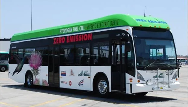
Within the project ZEBA demonstration includes 12 new generation fuel cell hybrid buses and two new hydrogen fueling stations [29]. The buses are 12 m, low floor buses built by Van Hool with a hybrid electric propulsion system that includes a UTC Power fuel cell power system (120 kW) and an advanced lithium-ion battery (rated energy: 17.4 kWh and rated power: 76 to 125 kW). Eight Dynetek, type 3 cylinders, 350 bars, are mounted on the roof. The new buses, Figure 11, feature significant improvements over two previous generations of fuel cell buses that were demonstrated in California, Connecticut, and Belgium. Improvements include a redesigned Van Hool chassis that is lighter in weight, shorter in height, and has a lower center of gravity for improved weight distribution. The bus has a top speed of 55 mph (88 km/h). The bus purchase cost is about $2,5 million.
Operating cost and fuel economy of fuel cell buses
Many transport operators continue to aid the FCB industry in developing and optimizing advanced transportation technologies. These in-service demonstration programs are necessary to validate the performance of the current generation of fuel cell systems and to determine issues that require resolution.
By the end of June 2011, nine of the twelve new Van Hool fuel cell buses had been delivered and seven of those were in-service. The buses have accumulated more than 80.000 miles (128.000 km) and a total of 7.653 hours on the fuel cell systems. The results presented here are early/preliminary information from the first five fuel cell buses that have been placed into service at AC Transit [29].
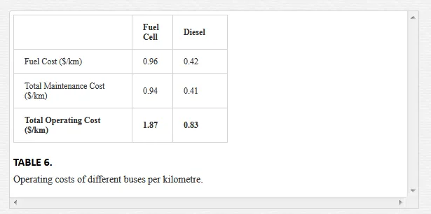
Table 6. presents the comparative test results for the Fuel cell and Diesel buses during the evaluating period.
During 2011, NREL completed data collection and analysis on new generation FCB demonstrations at three transport operators in the United States: SunLine California, CTTRANSIT Connecticut, and AC Transit California [30]. The current-generation FCBs in service at AC Transit, CTTRANSIT, and SunLine were all of the same basic design: Van Hool (12m) buses with ISE Corp. hybrid-electric drives and UTC Power fuel cell power systems.
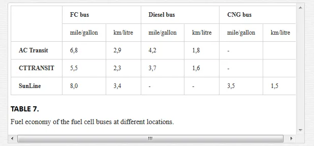
Table 7 shows the fuel economy of the buses at each location. Data are given in miles per diesel gallon equivalent and in km/litre (1mile per Gallon =0.425 km/litre).
The FCBs at the three locations showed fuel economy improvement ranging from 48% to 133% when compared to diesel and CNG baseline buses. This table also illustrates the variability of the results from fleet to fleet. The results are affected by several factors, including duty-cycle characteristics (average number of stops, average speed, and idle time). Average speed for AC Transit –9,8 mph (15,8 km/h); CTTRANSIT –6,5 mph (10,4 km/h), SunLine –13 mph (20,9 km/h) [30].
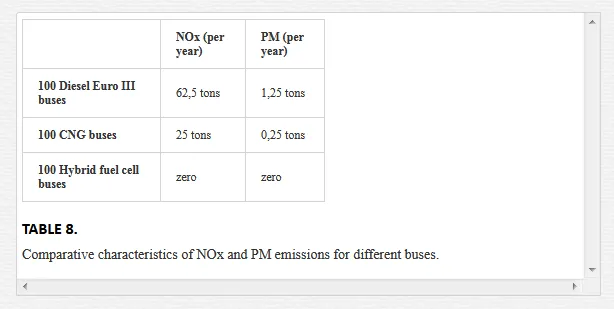
Data about NOx and PM emissions (per year) presented by Van Hool in its promotional materials for three different fleets of buses, are shown in Table 8 [31]. The data are calculated for 50.000 km per year, average speed 20 km/h, and power consumption 50 kW/h.
Equivalent emissions reduction potential of 100 hybrid fuel cell buses gives a CO2 reduction equal to the uptake of 3.100 acres of forest and a NOx reduction equal to 10 km of 4 lanes of cars [31]. The presented results show all the environmental advantages of the buses with fuel cell technologies.
Battery electric buses
Electric vehicles are a promising technology drastically reducing the environmental impact of road transport. At the same time, EVs are still far from proven technology. Reality is such that battery technology is simply not the whole answer. This is because (especially for large buses) batteries do not carry enough energy to power the bus for a full day.
According to IDTechEx report [32], “Electric Vehicles 2010-2020” it is estimated that worldwide there are about 480.000 electric buses, mostly small ones – with about 135.000 being bought each year as the fleets grow. Although only 12% of these new buses are electric, it is expected that by 2020 investment in the purchase of these buses will be measured in million of dollars. The main increase in electric buses will be running the free versions to be used without appropriate infrastructure along the route.
Full- size battery electric buses
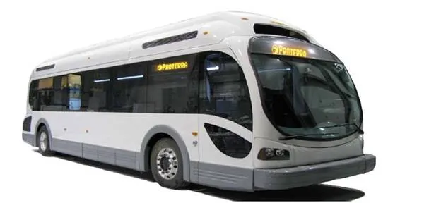
Proterra’s Battery Electric Bus: Proterra is the pioneering innovator and manufacturer of clean commercial transport solutions for city buses. Three Proterra’s zero emission fast-charge battery electric buses, EcoRide BE35, Figure 12, have been put in service in 2010 [33].
The buses feature Proterra’s revolutionary clean-transport technology, including the Proterra TerraVolt Energy Storage System, which allows a full battery recharge in less than 10 minutes. Additional bus features include:
- Flexible ProDrive and vehicle control system that can operate in battery electric mode or with any small APU to extend vehicle range when needed;
- Regenerative braking system, allowing the recapture over 90% of the vehicle’s kinetic energy available during braking;
- Light-weight composite body resulting in 25% reduction in weight, significantly lower maintenance costs and 40% longer life than traditional diesel buses
Proterra’s EcoRide BE35 battery powered buses can operate on standard routes for up to three hours—a range of 30-40 miles (48 to 64 km)—and after that, require just 10 minutes of charging to get back on the road. The buses can accommodate as many as 68 passengers and according to Proterra, will provide $300.000 in savings over the course of their lifetime thanks to lower fuel and transportation costs.
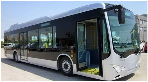
BYD electric bus: China’s Build Your-Dream (BYD) hybrid buses, Figure 13, were showcased during the 2008 Beijing Olympics. BYD has developed and is currently marketing a lithium-ion battery – powered hybrid-electric bus and all electric buses.
BYD, manufacturer of the first long-range (>300 km) all-electric bus (eBUS-12), has been selected as the sole eBUS provider for the 2011 International Universiade Games held in Shenzhen, China. At the core of the eBUS technology is BYD’s in-wheel motor drive system and the Iron Phosphate battery technology. The eBUS also integrates BYD solar panels on the bus roof, converting solar energy to electricity which is stored in the batteries and can completely offset the eBUS air-conditioning load (extending the range on sunny days) [34].
BYD has signed a Letter of Intent with the city of Frankfurt, Germany to introduce BYD’s all-electric, long-range, eBUS. BYD will supply three all-electric buses eBUS-12, two DC charging stations and technical support in the first quarter of 2012.
BYD is set to trial a full-size, all-electric bus in the Danish capital Copenhagen. Two K9 buses will initially be deployed on ordinary passenger routes from the second half of 2012.
The City of Windsor, Ontario has signed a letter of intent to purchase up to 10 BYD fully electric buses for the community’s transport services in 2012. It will become the first City in North America to launch long-range, all-electric buses. BYD has delivered over 300 all-electric buses worldwide and claims orders for over 1.300 more in 2012, making it the largest electric bus manufacturer in the world.
e-Traction buses: Netherlands’ company e-Traction (European integrator of low-floor fleet buses), delivered in the year 2010 the first of two e-Busz electric drive buses to Rotterdam’s public transportation authority. The e-Busz is a VDL Bus & Coach Citea CLF bus converted with the third generation of the e-Traction system [35].
e-Traction specializes in development of TheWheel as a direct-drive in-wheel motor system with integrated power electronics and fluid cooling. TheWheel is designed to deliver very high torque at low revolution. Since 2001, e-Traction is continuously developing in-wheel direct-drive motors for applications ranging from 400Nm to 10.000Nm per wheel. The vehicles with TheWheel save up to 40% traction energy and are 50% more fuel efficient compared to the standard diesel equipped bus. The e-Buzs is a “battery dominant” hybrid bus. This means that it has the ability to run on battery only, with the diesel generator turned completely off. The diesel unit (with diesel generator) can be replaced and, importantly, the bus returned to revenue service in roughly one hour.
In cooperation with e-Traction, Hybricon, a Swedish company converted two Volvo 7700 city buses to fully electric city bus with rapid charge technology. The buses with the name Arctic Whisper, Figure 14, are from November 2012 in public service in the city of Umeå, Sweden [36]. e-Traction and Hybricon removed the whole diesel driveline and replaced it with two e-Traction SM/500-3 wheel motors mounted on a rear axle construction. A 100 kWh Valence Li-Fe battery pack (for the purposes of the prototype) and pantographs for the charging station form the basic configuration, with a 50 kW diesel generator as the back-up system.
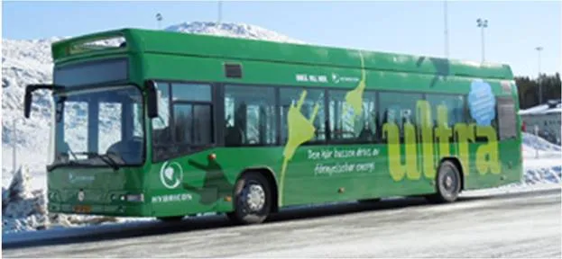
The Arctic Whisper’s bus is fast charged for 10 minutes at the end of its route to achieve nearly 100% all-electric operation but with the reliability of diesel. Without fast charging, the Arctic Whisper has an all-electric runtime of about 2-3 hours with the 100 kW batteries before the diesel generator needs to turn on.
Future plans include using different battery chemistries capable of faster charging and higher charging rates of over 200 kW as well as extending this architecture to 18 meter articulated buses.
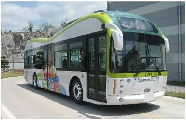
SMG battery electric bus: The Seoul Metropolitan Government (SMG) has started commercial operation of full-size battery electric buses since 2010, Figure 15. The government has been working on a project to develop the buses with local technology after reaching an agreement with Hyundai Heavy Industries and Hankuk Fiber back in September, 2009. It now has a goal of putting 120.000 of the vehicles to use in the city by 2020 – this will account for 50% of all public transport vehicles [37].
The SMG electric buses are a low floor design, 11,00 m in length and can travel as far as 83 km on a single charge. Using high-speed battery chargers they can be fully charged in less than 30 minutes and have a maximum speed of 100 km/h. Four battery charges are being provided. They use high-capacity lithium-ion batteries and regenerative braking. To reduce their weight and help maximize the distance they can travel between charges, these buses make extensive use of carbon composite materials, instead of metal.
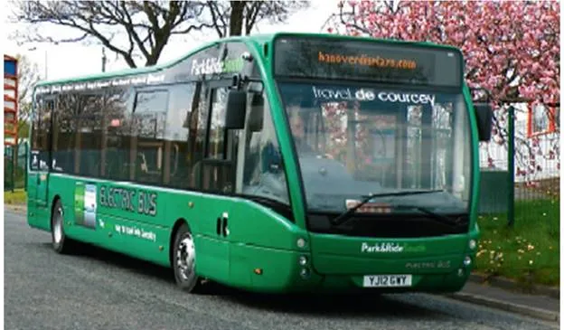
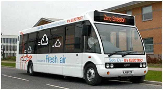
Optare’s battery-powered Versa: Optare’s battery-powered Versa, Figure 16 – the UK’s first commercial full-size battery bus which started on 1 April 2011 [38]. Battery-powered Versa buses are planned to be in service at peak times, providing a capacity increase on the 12-minute interval service. The buses can either be rapid charged, using a special charger, or slow charged. Travel de Courcey intends to re-charge the buses when they get to 30% of full charge. A return journey is around 5 miles (8 km). The Versa’s testing is currently underway with the first bus to be delivered, pending the arrival of the other two, and their entry into service. They are not the first electric vehicles to be commercially produced by Optare. It has already delivered Solo EV models, also used on short distance shuttle services [38].
Tindo solar electric bus: The Adelaide City Council’s electric solar bus, Figure 17, is the first in the world to be recharged using 100% solar energy. Recent advances in battery technology have helped the successful development of pure electric buses with a suitable range between recharges. The Tindo solar electric bus uses 11 Zebra battery modules, giving it unprecedented energy storage capacity and operational range [3
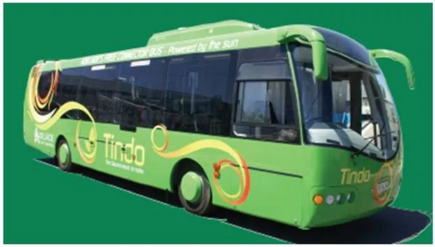
Some Tindo bus characteristic are: Length–10,42 m, Motor power peak – 160 kW, Motor power nominal – 36 kW, Speed – 76 km/h, Battery content – 261,8 kWh, Fast Charger Booster Power – 70 kW, Fuel costs – 50% lower than for a diesel bus, Range – 200 km between recharges under typical urban conditions.
Small battery electric buses
Optare solo EV battery electric bus: Optare offers the Solo EV, Figure 18, fully electric buses available in lengths of 8,1m, 8,8m and 9,5m. Replacing the usual diesel engine is an all-new electric drive, featuring an Enova Systems P120 AC induction motor rated at 120 kW and powered by two banks of Valence Lithium Ion Phosphate batteries. The two packs work in parallel and provide 307 V with a total capacity of 80 kWh. [40].
Around 4.000 Optare Solo EV buses in service worldwide produce zero tailpipe emissions. The model demonstrated in Switzerland is based on a standard 27-seat, 8,8 metre Solo, but the technology can be used on other models in the Optare range with higher passenger capacities. The Solo EV has been designed to perform exactly like a standard diesel powered bus, except that it is smoother, quieter and cleaner. It is completely traffic compatible, with good acceleration and hill climbing capabilities and a top speed of up to 90 km/h. On a full charge it has a range of around 110-130 kilometres depending on load factors and topography.
Solaris Urbino electric bus: Polish bus manufacturer Solaris developed the midi Urbino electric bus, Figure 19. The innovative electric bus is based on the 8.9 m Urbino family midi bus. At the heart of its power system is a 120 kW four-pole asynchronous traction motor supplied by Vossloh Kiepe. Energy is stored in two batteries weighing 700 kg each. These liquid-cooled lithium-ion batteries have a rated voltage of 600 V and the capacity to store 120 kWh [41].
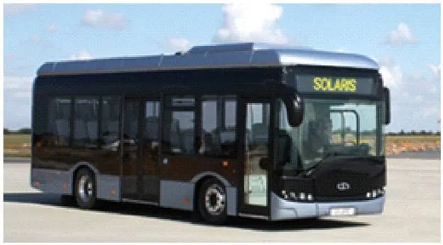
The battery capacity gives the Solaris Urbino electric a range of up to 100 km and a maximum speed of 50 km/h. Batteries are charged with a Walter plug-in connection. A full recharge from the 3×400 V, terminal takes as little as four hours. Even with the 1.400 kg traction batteries, the Solaris Urbino electric is only marginally heavier than its conventional counterparts thanks to the innovative lightweight construction employed.
Energy storage systems
Energy storage systems, usually batteries, are essential for electric drive vehicles. Batteries must have a high energy-storage capacity per unit weight and per unit cost. Because the battery is the most expensive component in most electric drive systems, reducing the cost of the battery is crucial to producing affordable electric drive vehicles.
The electrical energy storage units must be sized so that they store sufficient energy (kWh) and provide adequate peak power (kW) for the vehicle to have a specified acceleration performance and the capability to meet appropriate driving cycles. For those vehicle designs intended to have significant all-electric range, the energy storage unit must store sufficient energy to satisfy the range requirement in real-world driving. In addition, the energy storage unit must meet appropriate cycle and lifetime requirements. These requirements will vary significantly depending on the vehicle type (battery or fuel cell powered or hybrid electric).
There are many energy storage technology and battery chemistry and packaging options for electric drive buses.
Energy storage device used in some electric drive buses
Based on the presentation of realized solutions of electric drive buses, in the previous items of this chapter, it may be concluded that in the energy storage devices the latest technology batteries and ultra capacitors are applied. Summary of main characteristics of energy storage devices, for each of the presented buses is given in Table 9.
As can be seen from Table 9, Li-ion batteries are prevailing in the realized bus solutions. In the latest bus solutions Zebra battery and Iron Phosphate battery technology are used. It is notable that the energy capacity of energy storage devices BEBs are significantly higher than that of HEBs and FCBs.
In a HEBs with an ICE that recharges the battery (where battery operates in charge sustaining mode), a lighter and smaller battery is employed.
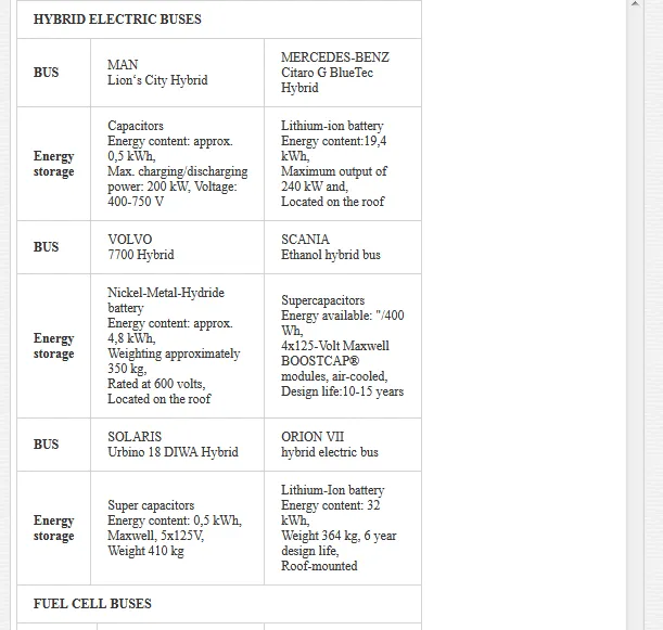
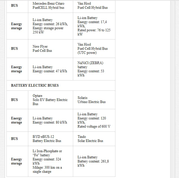
BEBs require a larger and heavier battery pack, to provide both high energy density and high energy storage capacity so as to maximize the range between recharges.
In the PHEBs one can expect smaller, intermediate-sized, battery packs capable of either charge-sustaining operation in the blended mode with an active ICE, or charge-depleting operation.
Current and future development of energy storage devices
A number of different battery technologies exist at present. The lead acid battery has been used to supply vehicle electricity for a number of decades. With the introduction of the first modern EVs in the 1980s, the need for more powerful batteries arose. Nickel-cadmium batteries were originally used, later replaced in hybrid vehicles by nickel-metal hydride batteries. However, none of these battery technologies provide the energy density required for sufficient driving distance in pure electric mode.
Recently, apart from the mentioned, other energy storage devices are in the intensive growth and expansion, such as: Lithium-ion battery (Li-ion), Li-ion polymer battery, Sodium Nickel Chloride battery (NaNiCl), Lithium iron phosphate battery (LiFePO4), Zinc Air battery, and Supercapacitors.
Based on available analysis and current battery data, it appears that the current (2010) battery life should exceed seven years and may be around ten years for ‘average’ use. The most promising chemistries appear to involve silicon, sulfur and air (oxygen) and another important development is research into nanotechnologies. These trends have been widely recognized and a recent presentation by Limotive researchers showed the following battery technology roadmap, Figure 20 [41].
Silicon is an attractive anode material for lithium-ion batteries because it has about ten times the amount of energy that a conventional graphite-based anode can contain [42]. It also has a specific energy of 1.550 Wh/kg – about four times the energy of a conventional graphite-based anode. Furthermore, silicon is the second most abundant element on the planet and has a well-developed industrial infrastructure, making it a cheap material to commercialize with a cost comparable to graphite per unit of weight.
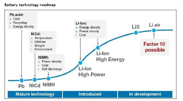
The problem with silicon is that it is very brittle and when lithium-ions are transferred during charge and discharge cycles, the volume expands and contracts by 400% which can pulverise the silicon anodes after just the first cycle.
The Li-Ion technology will become more and more the dominant technology for electro mobility. The Li-Ion technology has not yet reached its full potential, further improvements are still possible. Further developments are needed to improve capacity and lifetime, reduce volume and costs (currently around €250-€500/kWh for NiMH and €700-€1.400/kWh for Li-ion), and to be safe and reliable [43].
Although few serious technical hurdles remain to prevent the market introduction of electric powered vehicles, battery technology is an integral part of these vehicles that still needs to be significantly improved. Both current and near-term battery technologies still have a number of issues that need to be addressed in order to improve overall vehicle cost and performance. These issues include[44]:
- Battery storage capacity – Batteries for EVs need to be designed to optimize their energy storage capacity, while batteries for PHEVs typically need to have higher power densities.
- Battery duty (discharge) cycles – Batteries for various electric powered vehicles have different duty cycles. Batteries may be subject to deep discharge cycles (in all electric mode) in PHEVs or frequent recharge cycles through regenerative braking in conventional HEVs. Batteries for EVs will be subjected to repeated deep discharge cycles without as many intermediate cycles. Current battery deep discharge durability will need to be significantly improved.
- Durability, life expectancy, and other issues – Batteries must improve in a number of other respects, including durability, life-expectancy, energy density, power density, temperature sensitivity, reductions in recharge time, and reductions in cost. Battery durability and life-expectancy are perhaps the biggest technical hurdles to commercial application in the near-term.
Conclusions
A significant part in the future reduction of consumption of fossil fuels and of the corresponding reduction of emissions of harmful gases will be played by the alternative propulsion systems and alternative fuels. The development of electric drive technologies intended for application in buses is expanding. However, there are many limitations which at this stage slow down these developments. Sustainability of alternative propulsion systems is dependent upon the degree of their technological development and a compromise between the opposed economical, ecological, and social factors [45].
A large number of hybrid buses in North America and Japan and their intense development in Europe over the past several years is a confirmation that their number in the near future will be permanently growing. Although the sale of these vehicles is relatively small, the high cost of fossil fuels and the costs of hybrid vehicles becoming more acceptable will accelerate their further development. The hybrid buses are expected to contribute to further reduction of CO2 emissions, even though some manufacturers have reached the level of 30%. Further improvements in that direction will be dependent on the degree of hybridization of the propulsion system and electronic control which should contribute to the optimization of operation of ICE and hybrid system as a whole.
The experiences so far acquired, through the development of fuel cell buses and many demonstration projects around the world, are very positive. Some reports indicate that the performances of fuel cell buses in-service are above expectation. One of the many barriers to their wider use is the uncertainty of hydrogen supplies and high production costs of hydrogen. Other barriers are related to the security aspects of usage of these vehicles. Despite the insufficient performances of batteries, the next generation of fuel cell buses will be based on the hybrid concept and Li-ion batteries. Some predictions tell that fuel cells for buses will be commercially available within the next 10-15 years. At present, the high cost of buses is one of the greatest barriers to their commercialization.
Since 2010 increasing the number of battery driven vehicles and buses is evident, thus it can be expected that in the forthcoming times their number will continue increasing. However, barriers to their massive implementation will be the radius of movement, lack of infrastructure for recharging the batteries and, of course, high cost of the batteries and other power equipment (electric motors and control electronics).
Further challenges for electric drive buses will be the development of battery technologies and of other energy sources. Even though a considerable advancement has been made over the past several years by the development of Li-ion batteries, which have achieved energy density of 95-190 Wh/kg, there is still space for further advancements. The only battery chemistries that have a chance of achieving energy densities in the 1,000 Wh/kg range are rechargeable metal-air and other. Other non-chemical energy storage devices include super-capacitors that can reach very high specific power levels for a few seconds, but cannot hold a lot of energy.
The current generation of lithium-ion batteries typically uses a carbon-based anode and a metal oxide cathode. Research on next generation lithium batteries will continue the development of electrode and electrolyte materials and chemistries in order to increase the life and energy density of the battery while reducing size and weight. The most promising chemistries appear to involve silicon, sulphur and air (oxygen) and another important development is research into nanotechnologies.
Comments are closed