
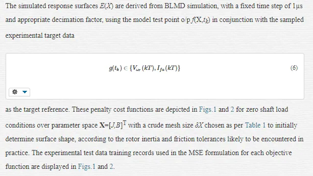
This chapter addresses the topographical examination of various mean squared error (MSE) cost surface structures and selecting the most suitable MSE fitness function for accurate brushless motor drive (BLMD) dynamical parameter system identification (SI) of BLMD shaft load inertia and viscous damping for electric vehicle controlled propulsion. The parameter extraction procedure employed here is in the offline mode for optimal drive tuning purposes during the installation and commissioning phase of embedded BLMD systems in high performance electric vehicle torque, speed and position control scenarios. Two types of penalty function, based on the transient step response of the permanent magnet (PM) motor shaft velocity and its stator winding current feedback in torque control mode [1,2], are examined here for arbitration of a suitable choice of cost objective function as the response surface in the accurate extraction of the BLMD dynamics. The choice of a particular MSE cost surface as an objective function in BLMD load parameter identification is motivated by the need for reliable tuning of the proportional and integral (PI) term settings during the drive installation phase for controller robustness and optimal performance in adjustable speed drive (ASD) or torque controlled embedded PM motor applications for electric vehicle propulsion. This chapter will focus on the mathematical analysis of embedded motor drive dynamical parameter identification over an MSE multiminima response surface with the following key results obtained:
a. the development of a novel quadratic mathematical model approximation for the investigation of the (i) nature of the MSE objective function and (ii) existence of a bounded MSE global minimum stationary region, based on transient step response motor current feedback signals, for mechanical parameter identification in sensorless drive torque control of electric vehicles.
b. the examination of the phenomenon of multiminima proliferation in the MSE cost formulation due to target data choice and ‘noisiness’ arising from evaluation of pulse width modulated (PWM) edge transition times during BLMD simulation [1,2].
c. the measurement of cost surface selectivity based on shaft velocity and current feedback target data and the decision favouring the choice of the latter data training record as the target function for dynamical parameter identification
d. the development of a novel parameter quantization metric to overcome cost surface ‘noisiness’, arising from computational uncertainty in the simulated PWM edge transitions [1], for avoidance of local minima trapping in the MSE cost surface during identification of the BLMD dynamics.
e. the development of a novel parameter convergence radius measure of encirclement of the cost surface stationary region global minimum, arising from the parameter quantization metric in (d), for determination of the bounds of accuracy that can be imposed on the returned estimates of the global optimum dynamical parameter vector during BLMD identification.
MOTIVATION
BLMD control tuning is necessary during the commissioning phase of embedded drives applications, for accurate torque and speed control in electric vehicle propulsion systems setup [3,4], accurate robotic end effector [5] or CNC tool positioning [6], where detailed apriori knowledge of expected drive load inertia and friction parameters are unknown to the electric motor drive supplier/manufacturer in the intended application beforehand. The choice of ASD [7] in high performance industrial applications, such as a small electric vehicle [4], robot manipulator [8, 9, 10] or machine tool feed drive [6,4], is usually based on consideration of a BLMD manufacturer’s catalogued specifications, relating to drive performance capabilities and limitations, by the customer or embedded drive equipment designer/manufacturer. The BLMD selection is often done independently of the motor drive manufacturer by the equipment designer for reasons of embedded systems design confidentiality and second sourcing of matching drive equivalents from different manufacturers for the purpose of cost reduction and embedded product protection from obsolescence via alternative drive substitution. The range of motor sizes available and spread of possible BLMD embedded applications has resulted in the provision of flexible drive tuning facilities with either manual or autotuning features [11] by motor drive manufacturers as a sales and marketing expedient to embedded equipment designers. This flexible approach to drive tuning policy eliminates the need for the BLMD manufacturer to participate in the detailed design of embedded drive applications except in the provision of motor drive systems with high output torque and speed ranges to cater for a range of anticipated high performance applications [12,8,13]. BLMD systems with high peak current capability and fast response times due to low PM rotor mass are designed [6, 7] to handle large inertial load torques [14] experienced in robotic applications [4, 5] and electric vehicle propulsion systems, with a no-load to full-load inertia variation [9] of 10 is to 1. It is in response to this background of applications diversity, regarding the particular design details of embedded drive products about the size of inertial loads and friction coefficients encountered [4,6,9], that the present work on cost surface analysis for parameter extraction in electric vehicle control is directed from a motor manufacturer’s perspective.
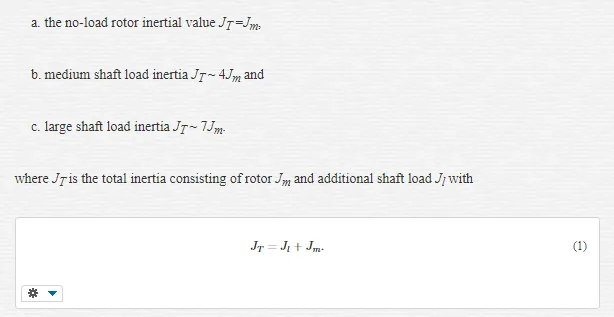
Since the possible variation in the load dynamics of an intended BLMD application is unknown at the outset the initial task here for an end user is to identify the actual load inertia and friction coefficients experienced during startup of a given embedded drive in the offline mode for robust PI controller tuning [15]. In this scenario the customer has the flexibility of manually tuning the BLMD speed loop, which is provided as a PI adjustment option along with procedural details for tuning by the motor manufacturer, during the setup and commissioning phase for a particular ASD application. The challenge then posed for the motor drive designer in this instance is the provision of an automated tuning facility for the velocity or torque loop during the commissioning stage thus eliminating the need for any manual input by the customer. This feature requires the identification of a fixed embedded load configuration during setup and subsequent automated optimal configuration of the velocity controller PI terms [15]. In the absence of embedded load information the cost surfaces and identification methods investigated here focused on inertial load spreads for vehicular and robotic applications [9] of up to ten times the inherent motor shaft inertia as recommended by the BLMD manufacturer for the drive [16] modelled in [1].
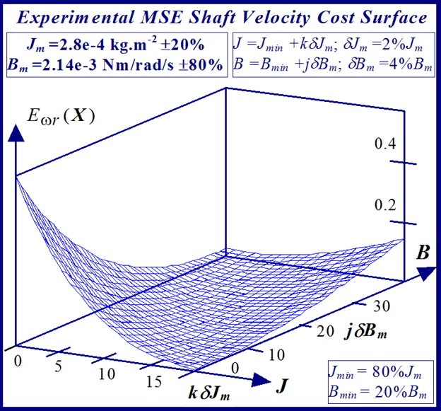
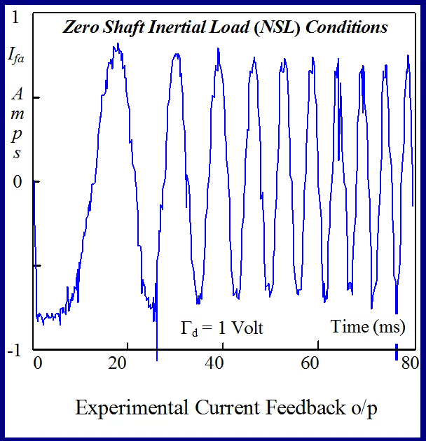
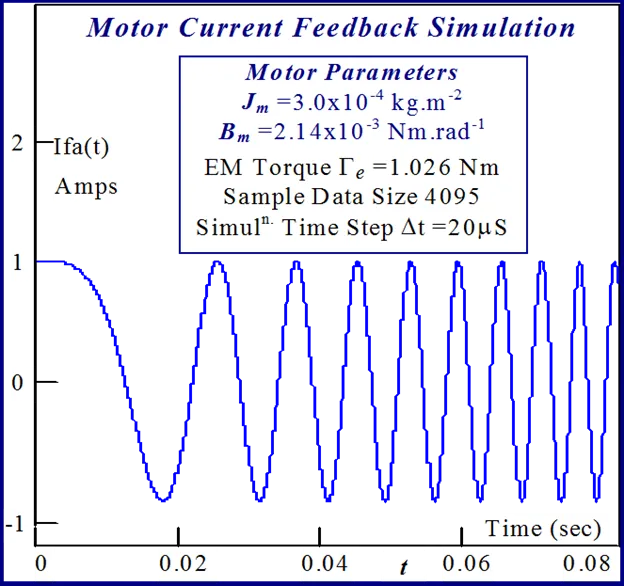
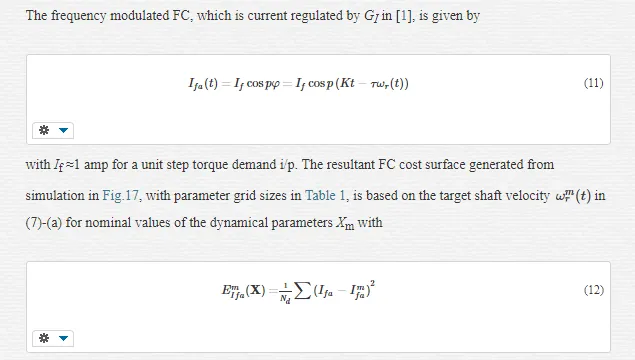
The concept of a simulated cost surface is developed here [17] as an objective function to facilitate parameter extraction of the installed drive dynamics, during offline BLMD system identification, with MSE minimization. This methodology provides useful insight into the nature and formulation of the most suitable MSE objective function to be minimized, based on actual drive experimental test data available and BLMD model simulation, coupled with an effective system identification (SI) strategy for accurate motor parameter extraction [18]. This approach can also be used as an alternative means of providing the optimal set of extracted parameter estimates from inspection of the global minimum location on the simulated cost surface with embedded local minima. Furthermore it can be used as a basis for comparison of the effectiveness of the actual identification search strategy deployed in terms of the accuracy of returned parameter estimates. The problem of inertia (J) and friction (B) parameter extraction of an actual BLMD system over a sinc function shaped multiminima cost surface [19], based on step response feedback current (FC) target data which has a constant amplitude swept frequency characteristic, is investigated as a test case using response surface simulation.
The global minimum estimation, from response surface simulation discussed in section 2.0 below, is targeted towards offline identification of the fixed dynamical load possibly encountered by an embedded BLMD system during the setup and commissioning phase. This is necessary for optimal tuning of the installed BLMD velocity and position loops in any high performance electric vehicle and industrial application. The present work on optimal parameter estimation is mainly concerned with the offline identification of the worst case inertial load that could possibly be experienced by an installed embedded BLMD. This is articulated here through BLMD simulation in torque control mode, using the full reference model developed in [1, 2], and drive experimental step response measurements with three known test cases of shaft load inertia, for validation of the accuracy of the parameter identification strategy, corresponding to:
shaft velocity target data with measurement data length in the reduction of cost surface curvature in the vicinity of the global minimum. These current feedback step response attributes arbitrate in its favour as the most suitable choice of target data in MSE cost function formulation.
In the absence of embedded drive application details from the BLMD manufacturer [17] no precise limits on the desired accuracy of the returned J and B parameter estimates could be affixed to the parameter identification strategy for velocity controller tuning purposes in the commissioning phase. However the use of a quantized metric δXL, as mentioned previously, in parameter space puts a limit on the parameter resolution accuracy possible during identification of the BLMD dynamics in electric vehicles. It should be noted that without the imposition of this parameter quantization strategy there is a risk of false minimum trapping of the identification search algorithm in a ‘noisy crevice’ [18] in a side-wall of a cost surface, besides local minimum capture, well away from the global minimum estimate. This novel quantization procedure in parameter space, which eliminates the effect of simulation step size related computation induced noise, results in the availability of a smooth cost surface over which a parameter identification search algorithm will work and converge to an optimal estimate [17,18,21]. One other benefit of the parameter quantization process is that it divides up parameter space and restricts the identification strategy to a countable number of parameter lattice points [18] and thus minimizes the search time to global optimality.
A further aspect of concern besides false minimum trapping is that all optimization algorithms for BLMD parameter identification proceed in a continuous search of parameter space to a convergence estimate of the parameter vector sought with an end stopping criterion [22,23]. The norm of cessation of the optimal parameter search strategy is generally based on the smallness of cost reduction over successive iterations within a specified error bound ε at termination. The termination criteria are generally not focused on the smallest percentage variation of the parameter estimates acceptable. However with the quantization δXL of parameter space for response surface smoothness, limits for parameter resolvability can be imposed by restricting the identification search process to an integral number k of quantum steps kδX commensurate with the percentage accuracy %X required in absolute terms such that %X = kδX. This restricted step approach, in terms of the specified parameter accuracy sought for BLMD tuning purposes during the setup and commissioning phase, can reduce the SI computation time to optimality [18].
Response surface simulation and analysis [17]
The concept of a simulated response surface (RS) is presented as an aid to motor dynamical parameter optimization in high performance Brushless Motor Drive (BLMD) identification with a multiminima objective function. This methodology provides useful information concerning the formulation and nature of the most suitable objective function to be minimized, based on actual drive experimental test data available and BLMD model simulation, coupled with an effective system identification (SI) strategy for accurate motor parameter extraction. This simple approach, although computationally intensive, can also be used as an alternative means of providing the optimal set of parameter estimates from inspection of the global minimum location on the simulated cost surface with embedded local minima. Furthermore it can be used as a basis for comparison of the effectiveness of other identification search strategies deployed, such as the Powell Conjugate Direction search method [18] and Fast Simulated Diffusion algorithm [20,21], in terms of the accuracy of returned parameter estimates. The problem of inertia J and viscous friction B parameter extraction of an actual BLMD system over a sinc-function (sinx/x) shaped multiminima cost surface, based on step response feedback current (FC) target data which has a constant amplitude swept frequency characteristic, is investigated using response surface simulation. The choice of the FC target data is based on its excellent coherence properties [24] from step response testing, for checking BLMD model fidelity and accuracy and for the penalty cost function formulation in SI. This difficulty with a multiminima objective function converging to a non optimal parameter estimate, associated with the adoption of the FC target data for motor parameter identification, is examined in the FSD method [20, 21]. An explanation is provided as to the existence of local minima plurality with the observed FC target data used in the sinc-like penalty cost surface generation. All classical optimization techniques [22], with the exception of modern statistical methods [21], are known to have difficulty with this type of cost surface in identifying the optimal parameter vector. The problem arises with initialization of the search strategy far from the global minimum resulting in possible local minimum trapping and non optimal convergence of the cost minimization algorithm during the parameter extraction process. This response surface [RS] methodology, however, provides a simple and effective alternative to classical methods in acquiring an accurate estimate of the global minimum. Results are presented, which demonstrate the efficacy and reliability of the RS method in returning accurate estimates for ‘known’ values of the BLMD shaft dynamics. The application of this FC step response related multiminima cost function in parameter extraction is compared with the alternative parabolic shaped shaft velocity objective function for cost surface selectivity in the vicinity of the global minimum and for accuracy of the returned identified parameter estimates. A mathematical approximation analysis is provided for verification of the cost surface shapes resulting from the deployment of step response FC and shaft velocity as target data in objective function formulation.
COST FUNCTION FORMULATION [18]
Response surface simulation is a useful graphical tool [25] in system identification and can easily be applied to motor parameter extraction and BLMD model validation. This visual concept, which has been used in process control optimization [25], provides an intuitive insight into the topographical structure of the cost function to be minimized and the rapid location of the global minimum. It also provides information on the most suitable identification search strategy that should be adopted in parameter space to obtain an accurate estimate
Xˆopt={xˆ1 opt,xˆ2 opt}TX^opt={x^1 opt,x^2 opt}T
of the motor dynamics where the inertia J ≡ x1 and viscous friction B ≡ x2 are the coded variables. The location of the global minimum stationary point can be obtained by inspection from the simulated cost surface. This approach, although computationally expensive, can be used to secure an independent alternative optimal estimate
X¯¯¯opt={J¯¯opt,B¯¯¯opt}TX¯opt={J¯opt,B¯opt}T
as a reference against which the accuracy of other parameter identification search schemes such as the Fast Simulated Diffusion [26] can be judged.
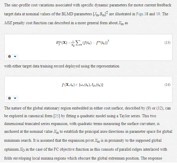
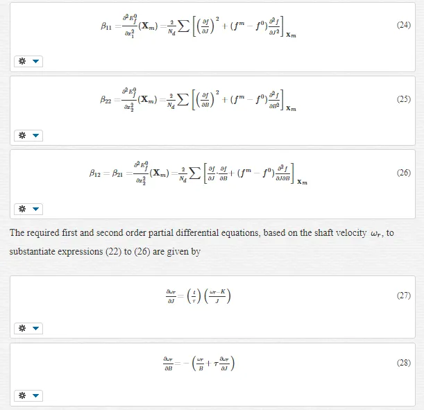
BLMD parameter extraction is generally based on the minimization of the errors of fit ek between the observed motor drive target data and BLMD model responses in terms of the controlled parameter vector X. This identification process results in the adjustment of the J and B parameters towards global optimality. The search strategy is performed in the neighbourhood of the global extremum using the least squares error criterion in the cost function formulation between each value of a time series
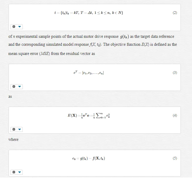
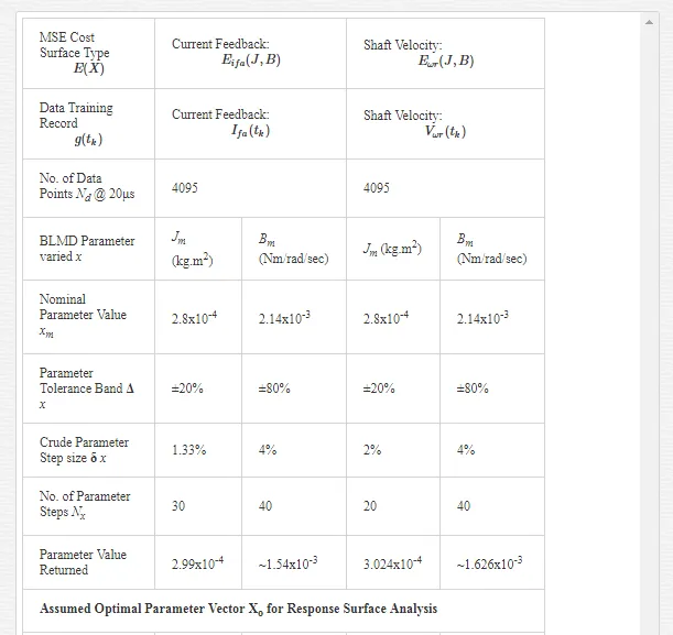

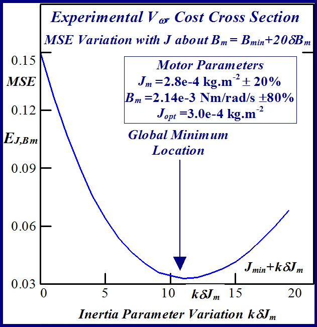
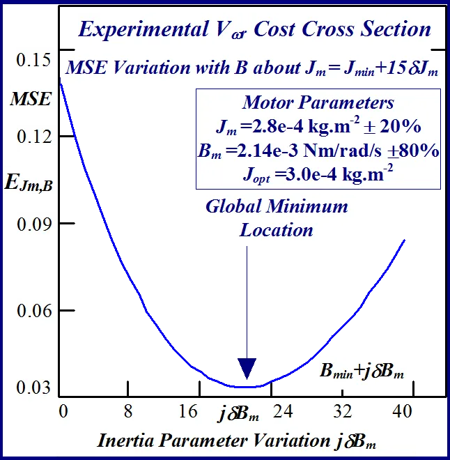
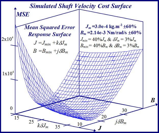
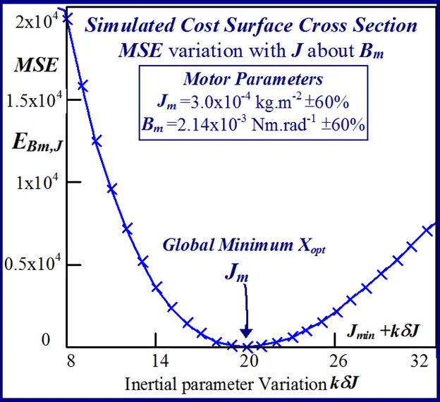
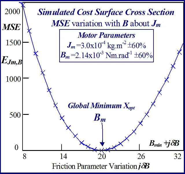
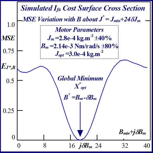
The anticipated variation in the search cost, likely to be encountered during BLMD system identification (SI) over the parameter tolerance band of interest, can be gauged from cross sections through the chosen response surface at nominal values of the rotor parameters [Jm,Bm]T. The cost variations associated with specific dynamic parameters are illustrated in Figs.5 and 6 for motor current feedback and in Figs.7 and 8 for shaft velocity target data. These cross sections provide important information regarding the surface shape and curvature and consequently about the nature of the stationary points found and type of SI search algorithm that should be deployed over such hitherto surface ‘terra incognita’.
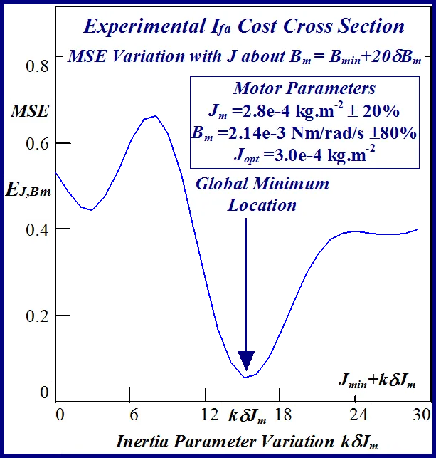
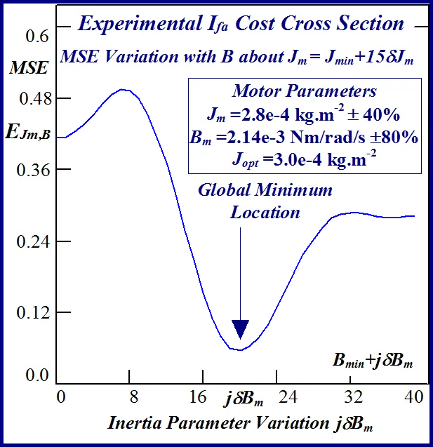
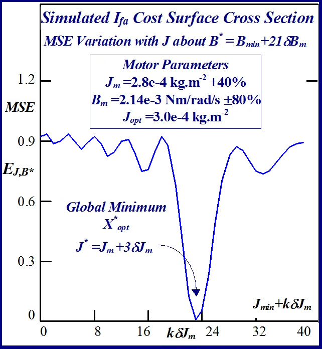
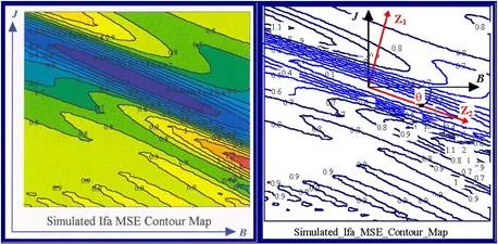
The FC cost ‘landscape’ highlights the existence of several parabolic shaped ridges, interspersed with embedded synclines within its sinc-like folded topography, with a consequent plurality of local minima. The cost terrain also shows the presence of a stationary elliptical shaped ridge system centrally located in the contour map of Fig. 9 with the possible existence of a ‘line minimum’ [25] along the principal/major axis. These multiminima folds are manifested in the constructive and destructive interference patterns encountered in the frequency ramp up of the FC sinusoid, when compared with the optimal parameter reference or test data waveform, during the transient phase of motor acceleration. The shaft velocity cost surface is parabolic shaped as seen from the contour map in Fig. 10 but is less selective than its FC equivalent in the vicinity of the global minimum when the respective cost surface cross sections with equivalent parameter grid sizes are compared.
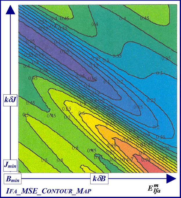
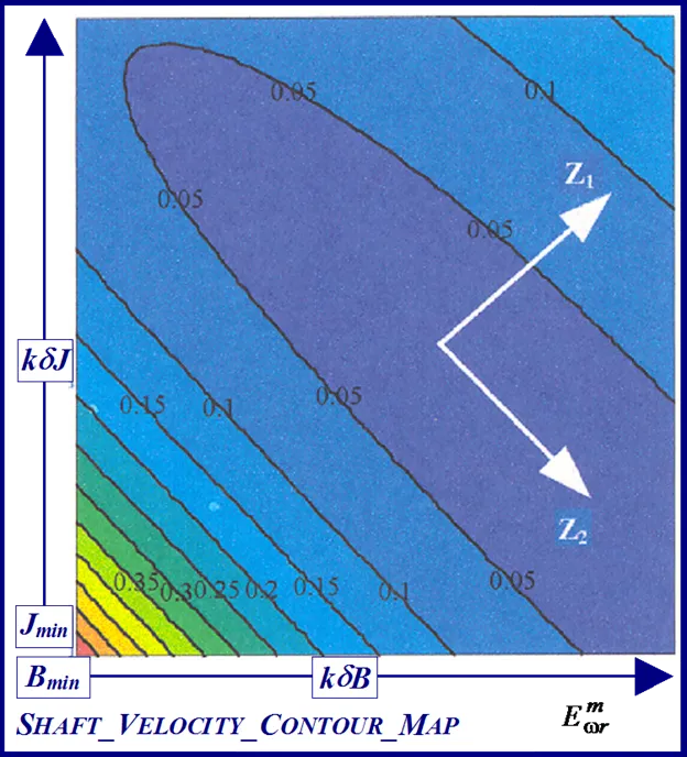
It is evident from Figs. 9 and 10 that both objective functions possess long wedge shaped stationary valleys in the response surfaces with no ‘apparent’ clearly defined global minimizer. The observed near linear dependence of the surface shape on the parameters in a ‘line minimum’ along the valley floor indicates that B is commensurate with J in the ratio J/B which is the dynamical time constant τm of the motor. The B parameter, which is the least likely of the two to vary in the electromechanical drive applications [8,9] can to be acquired from dynamic testing as per [1] to free the other parameter for identification purposes. This reduces the identification problem to single parameter extraction in J or alternatively in τm, where parameter decoupling is non essential, for controller design purpose.
Response surface simulation provides an alternative route of accurately estimating the optimal parameter vector Xopt by means of inspection of the surface minimum cost. This method, although computationally expensive, can be used as a yardstick by which the overall convergence performance of other identifications schemes [21] can be contrasted, such as FSD, over a range of motor shaft inertial loads. The response surfaces can be simulated initially using a coarse parameter mesh size, for a range of supposedly ‘unknown’ motor inertial load test cases for shaft velocity and current feedback MSE objective functions, for rapid location of the global minimum. Further refinement in mesh size can be made down to the parameter step sizes necessary in the vicinity of the global minimum for accurate resolution of the optimal parameter set. Results, which demonstrate the accuracy and effectiveness of RS simulation, are presented for global minimum estimates of motor shaft inertia which are in close agreement with known test inertial load values.
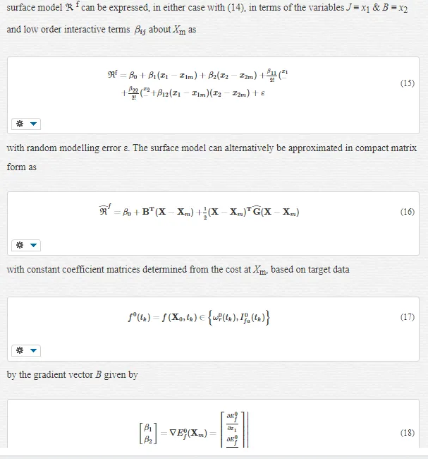
NOVEL MATHEMATICAL ANALYSIS OF RESPONSE SURFACE [18] – MODELLING AND SIMULATION
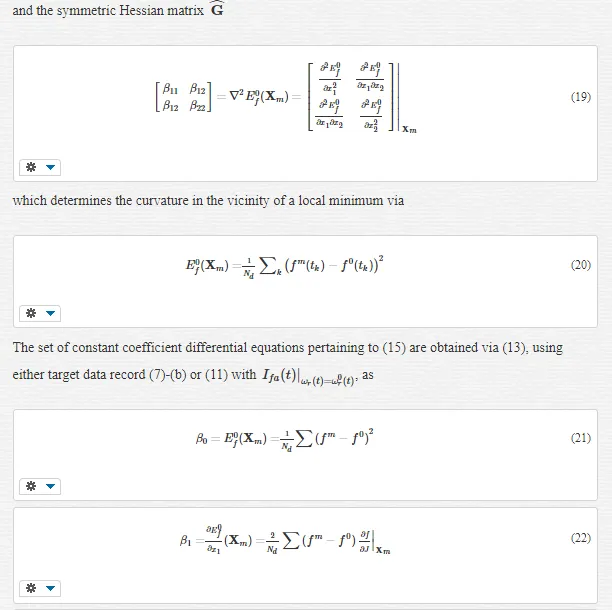
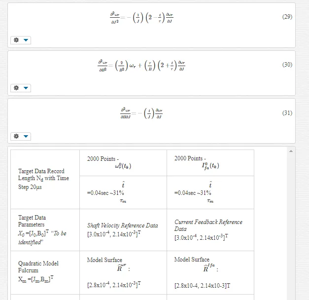
Response surfaces can be generated for the BLMD shaft velocity and current feedback step responses, as the mean squared error cost function between an actual drive experimental target data record and simulated model responses, by varying J and B over the two dimensional dynamical parameter space of interest. This graphical procedure is then used to shed light on the shape of the respective cost surfaces and to make a decision as to the most efficient parameter identification strategy to be deployed in each case. Inspection of each of the 2-D MSE response surfaces reveal the existence of ‘open’ wedge shaped stationary regions principally in the B-parameter direction containing what appears to be a global ‘line’ minimum in both cases. From a parameter identification perspective such open stationary regions would mean an infinite number of admissible solutions and thus uncertainty in the parameters extracted. The presence of such a difficulty would require careful measurement of one the parameters, in this case the friction as this is the principal direction that the line minimum appears to exists, in order to free the other (J) for identification. A novel mathematical analysis is presented in this chapter to determine whether or not these embedded stationary regions are open. This approach is articulated by formulating a simple quadratic model approximation of the cost surface stationary regions over a small neighbourhood of parameter space, with interacting J and B terms, for proposed model accuracy. The BLMD model step responses are also approximated by simple analytical expressions over response time spans that are very short by comparison with the dynamical time constant
τmτm
for validation and accuracy of the response surface quadratic model approximation. These simple step response representations, in which the parameters J and B can be adjusted over the space of interest for local cost surface generation and analysis of the stationary region, are included along with the relevant experimental target data in the cost surface quadratic model approximation. This mathematical analysis, employing the simplified quadratic model for both cost surfaces, can be used to show:
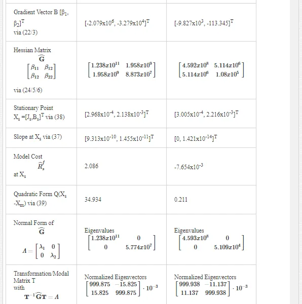
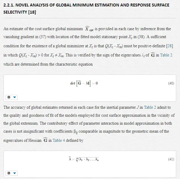
· that the stationary regions for the current feedback and shaft velocity objective functions are closed and bounded indicating the presence of a trapped global minimum,
· how closely the dynamical J and B parameters are coupled by making a comparison of the extracted quadratic model eigenvalues,
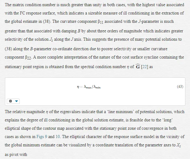
· that a line minimum exists principally in the B parameter direction and quantifies the extent of this B-line minimum by the eigenvalue ratio
· establishes the degree of ill conditioning for the global minimum solution parameter vector estimate XS extracted from the minimized quadratic model.
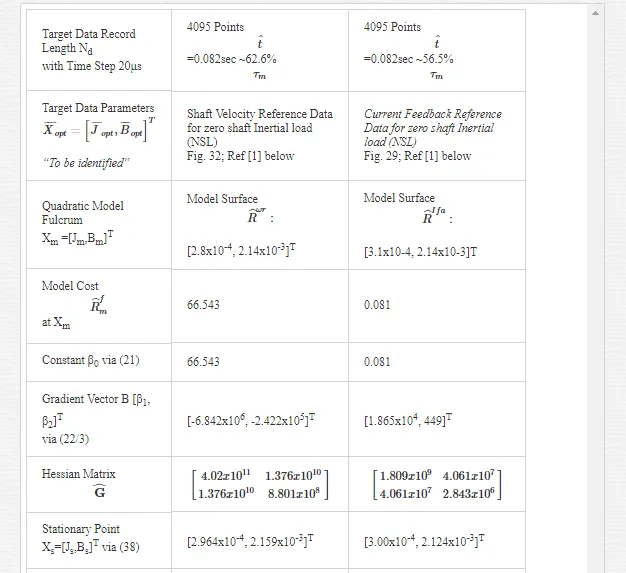
Furthermore this analysis also demonstrates that the current feedback response surface has better selectivity in the global stationary region than the shaft velocity equivalent with increasing data record lengths. This outcome helps in the decision analysis that favours the use of current feedback target data in cost function formulation for dynamical parameter identification.
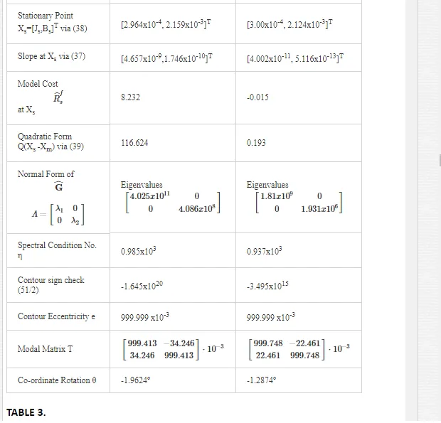
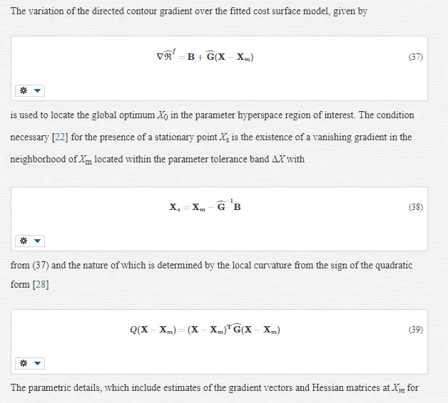
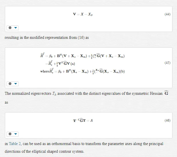
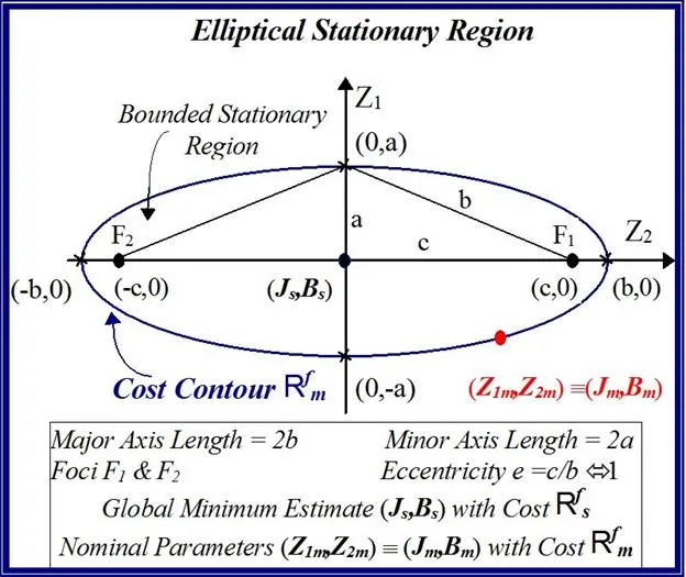
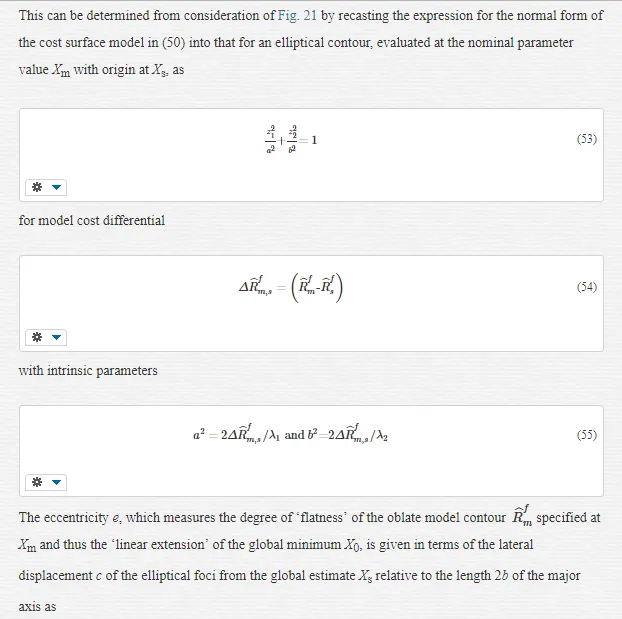
elliptical contours rather than contained within an open wedge shaped response surfaces with no define convergence zone. The degree of elliptical eccentricity e of the trapped stationary zone quantifies the extent of the ‘line minimum’ of global minimum convergence, congruent with the major axis, as notionally illustrated in Fig. 21.
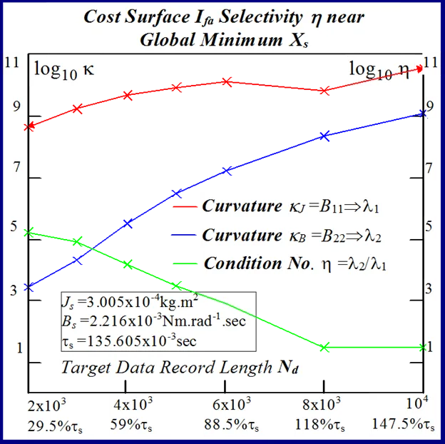
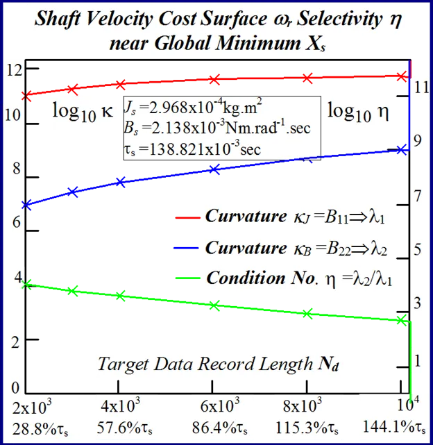
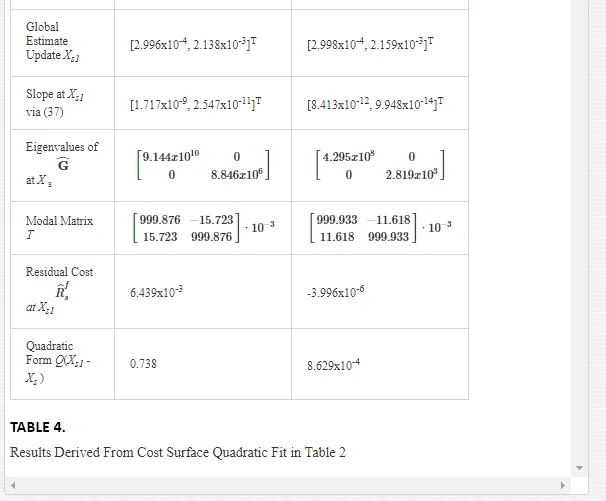
The degree of model selectivity is three orders of magnitude greater in the case of the motor inertia for actual measured target data employed in both response surface approximations as evidenced from the spectral condition number in Table 3 and in Table 4 for simulated target data trials. Consequently this selectivity margin renders a more accurate estimate in the extracted J-parameter which is mirrored by the arguments leading to the feature size ratio in (57). The cost surface selectivity improves along the principal axes of the normal form when the target data length Nd is extended as indicated by the increased magnitudes of the eigenvalues in Tables 4 and 3. This trend in enhanced J parameter selectivity, which is a measure of the accompanying increase in curvature at the global extremum, is displayed in Figs. 22 and 23 for increasing data record lengths and is a manifestation of the narrowing of the cost surface fold containing the directed ‘line minimum’ principally in the B-parameter direction. The selectivity improvements are greater for increased FC step response data record lengths in Fig. 22than those for shaft velocity target data in Fig.23. This due to the appearance of more FC cycles with reduced periodicity as motor speed increases demanding a greater degree of fitted model accuracy, with smaller margins of error in terms of frequency and phase coherence at the global minimum value, in the extraction of the optimum parameter vector XO during system identification. The shaft velocity step response by contrast losses its excitation persistence with transient speed decay as it evolves towards steady state conditions with increased data capture time. After a sufficient time elapse the target data transient information, responsible for velocity cost surface folding, is submerged by the steady state onset of maximum motor speed conditions. This irretrievable loss of target velocity signal amplitude variation with time results in a reduction of surface selectivity with parameter variation near the global minimum. These considerations admit to a better choice in the current feedback as a suitable candidate for MSE objective function formulation where accurate parameter extraction is essential during the identification phase of optimal controller design in high performance adaptive BMLD systems for electric vehicle mobility. Furthermore the increasing trend towards motor sensorless control [30] obviates the need for separate rotor position sensors with essential information obtained from the motor signature current via FC sensing at the inverter controller o/p. This adoption of sensorless operation in motor drive systems lends added importance to observed FC data as a suitable target function during parameter identification.
Response surface noise and parameter quantization
The computation ‘noise’ inherent in the MSE penalty function construct, based on simulated target data at nominal machine parameter values, is manifested as response surface roughness in parameter space. This is due to model nonlinearities and coarseness of evaluation of the PWM switching instants and results in ‘false’ local minima proliferation in the neighborhood of the global minimizer.
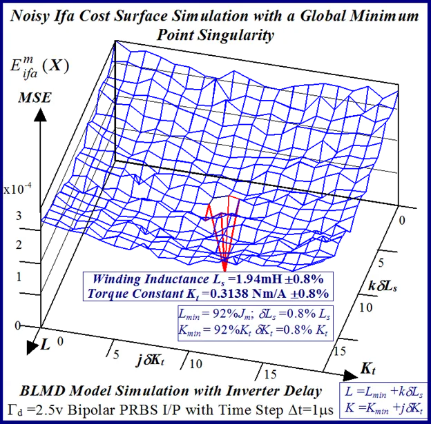
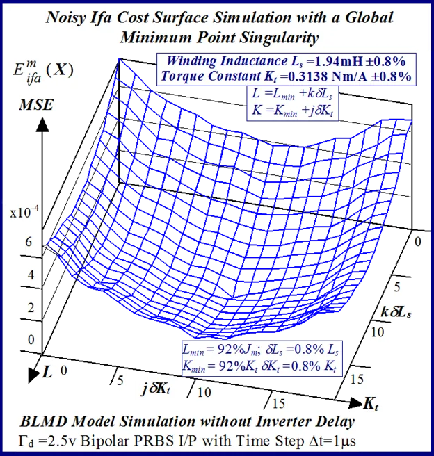
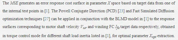
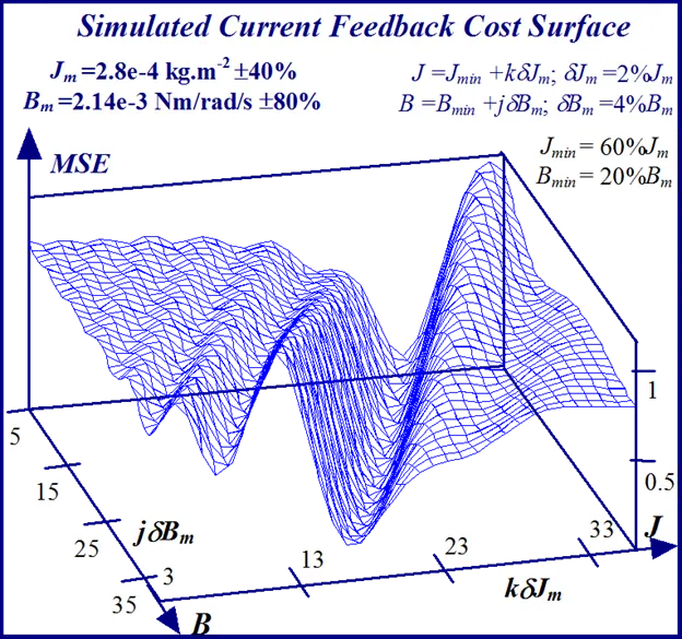
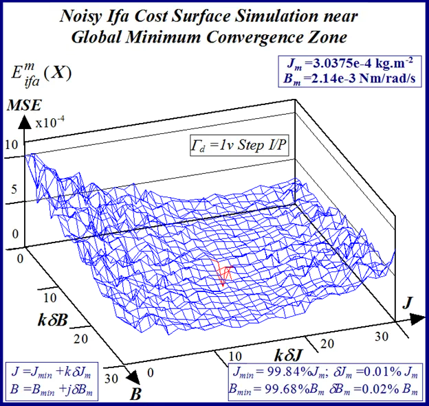
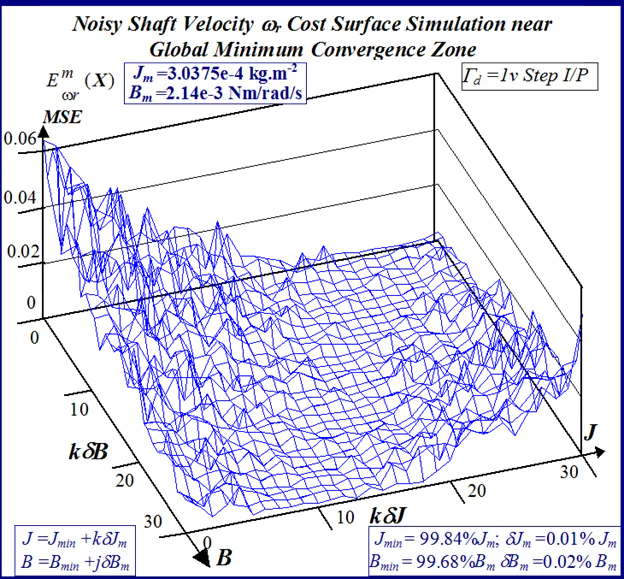
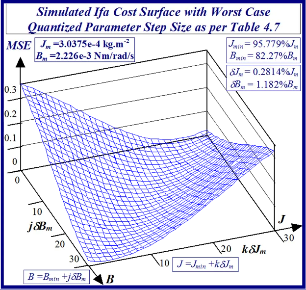
A typical example of this is illustrated in Figs 24 and 25 for BLMD model simulations, with and without inverter turn-on delay δ considered, for small step change variations in the stator winding inductance LS and torque constant Kt parameters. These response surfaces were obtained from BLMD simulation, using FC target data for nominal parameter values as in [1], with a 4095 bit maximal length 2.5 volt bipolar pseudorandom binary sequence (PRBS) input stimulus. The response surface in Fig.24has a very shallow paraboloidal shape for the small parameter tolerance ranges chosen with a rough noisy texture peppered with local minima in the vicinity of the point-like global minimum. The response surface for simulated FC target data is relatively smooth in the absence of inverter delay turn-on with a point-like singularity at the global minimum as shown in Fig.25. The cost functions pertaining to simulated step response FC Ifa and shaft velocity ωr target data, displayed in Figs.26 and 27 for the dynamic parameters {J,B}, are also noisy with point-like multiminima scattered around the ‘pinhole’ stationary point as in the former case. These surfaces are parabolic for very small tolerance ranges selected near the global minimum as in the main lobe of Fig.1 for the FC corrugated surface.
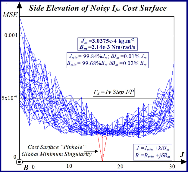
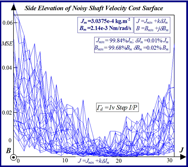
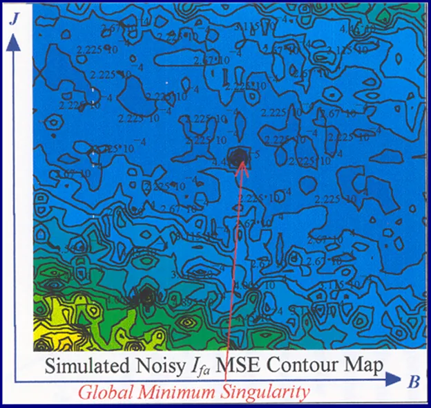
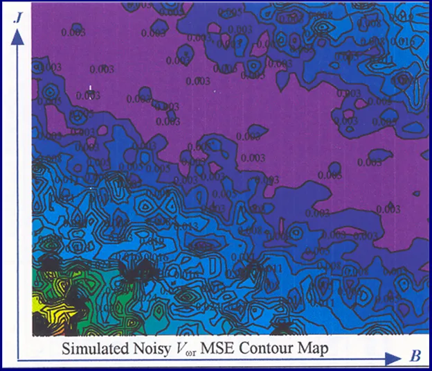
In the simulated velocity response surface shown in Fig.29 a stationary region exists at zero floor cost with no definite observable global minimum point. An alternative perspective of the minimum stationary regions is provided by the contour maps shown in Figs.30 and 31 for FC and shaft velocity target data respectively. The existence of the point-like global minimum singularity with surface noisiness is clearly evident from the level contours in the FC surface relief map. In the case of the shaft velocity response surface the presence of ‘noisy’ local minima strewn over the ‘river bed’ syncline of the global minimum stationary region is clearly defined by the contour map in Fig.31. The occurrence of ‘noisy’ local minima in the above error surfaces presents a difficulty to any classical optimization method in acquiring the global minimizer where fine parameter resolution is concerned.
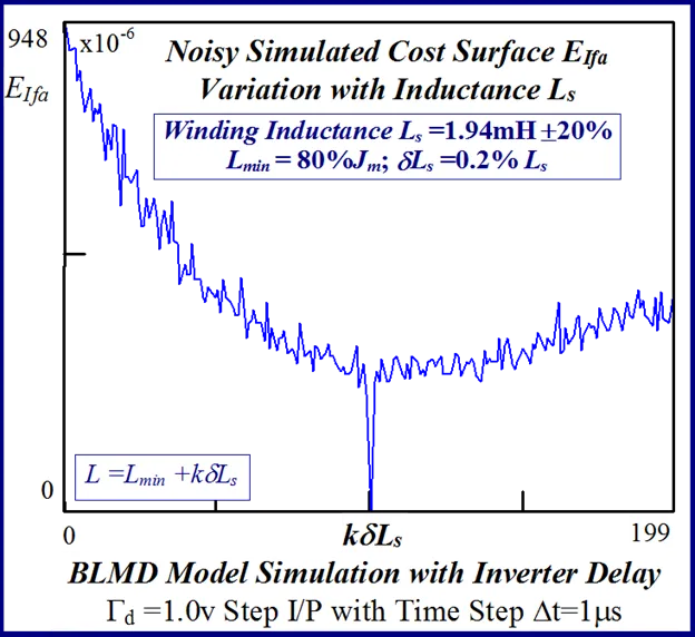
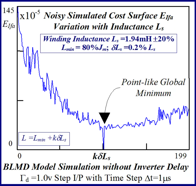
A more detailed examination of the effect of inverter delay, achieved through BLMD model simulation without current controller o/p saturation using a 1 volt torque demand step i/p, on the one dimensional MSE response surface in Fig. 32 for very small inductance variation reveal a granulated profile which is less pronounced than that in Fig. 33 with the absence of delay.
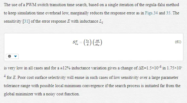
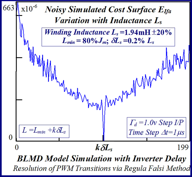
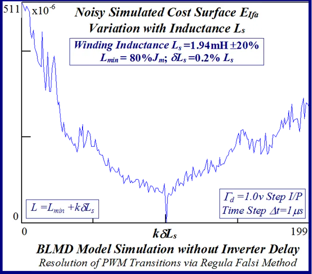
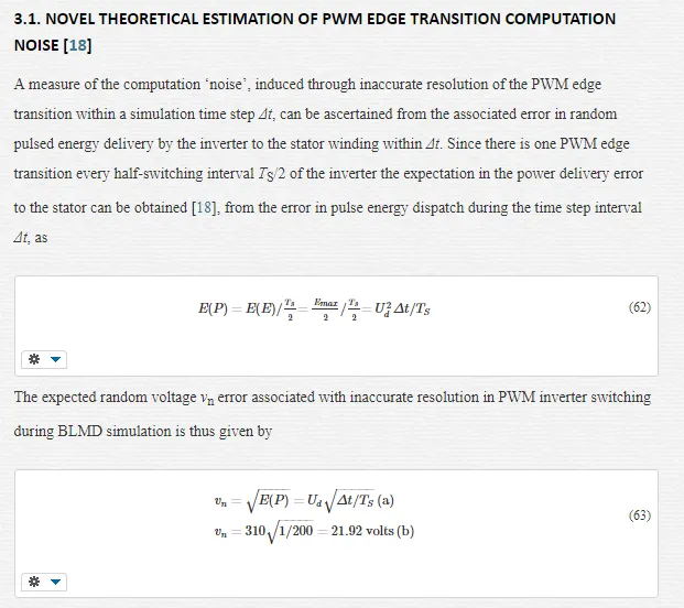
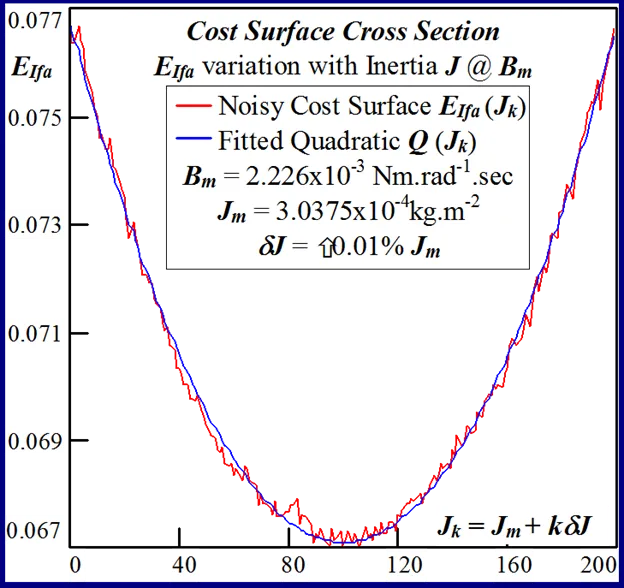
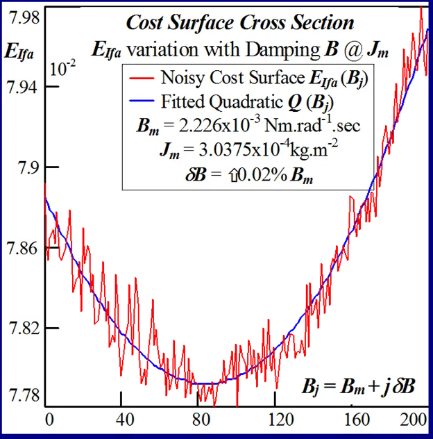
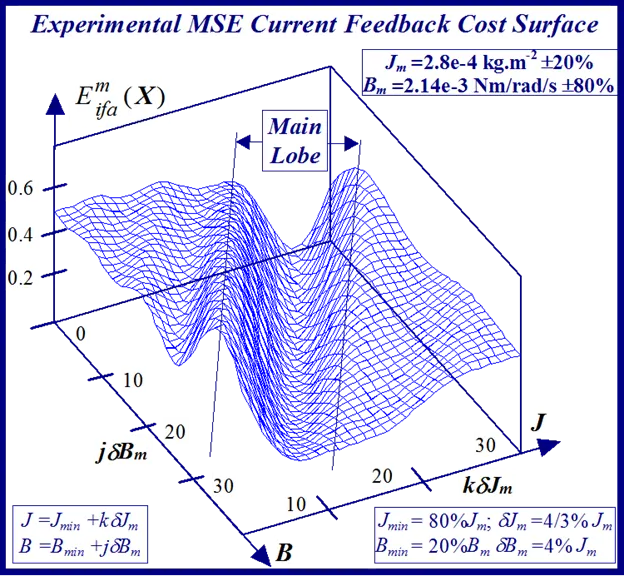
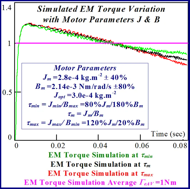
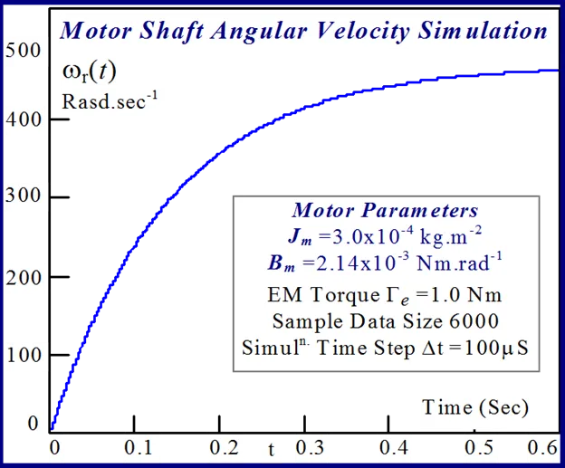
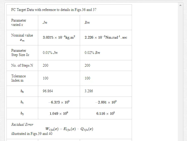
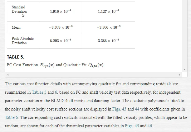
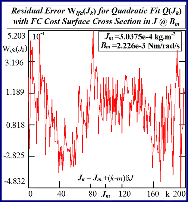
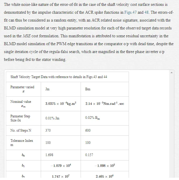
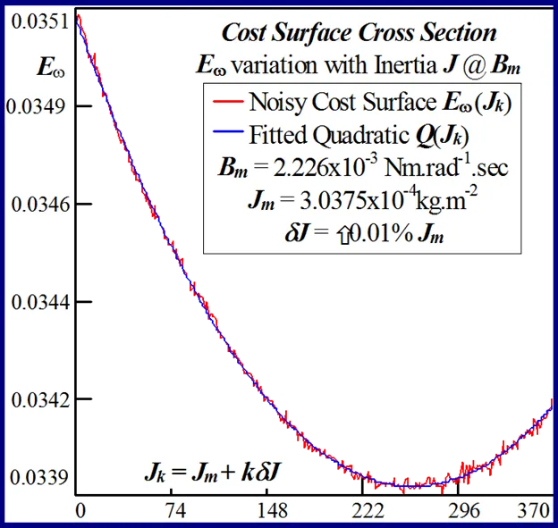
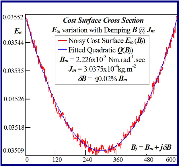
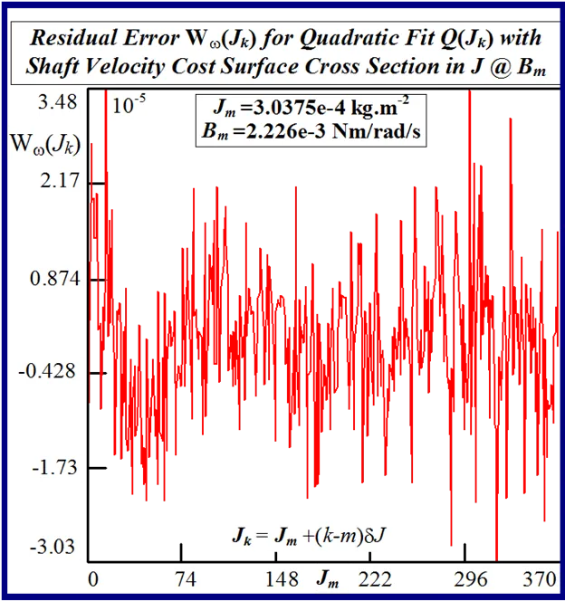
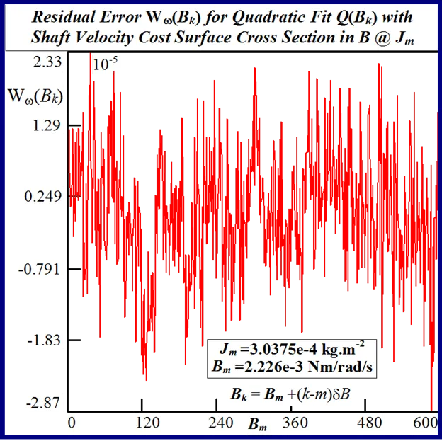
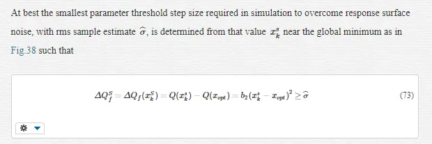
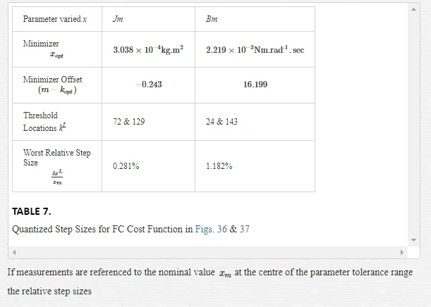
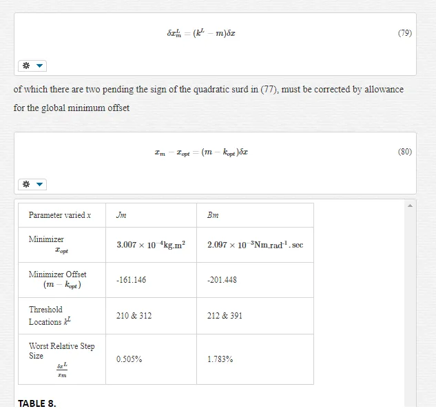
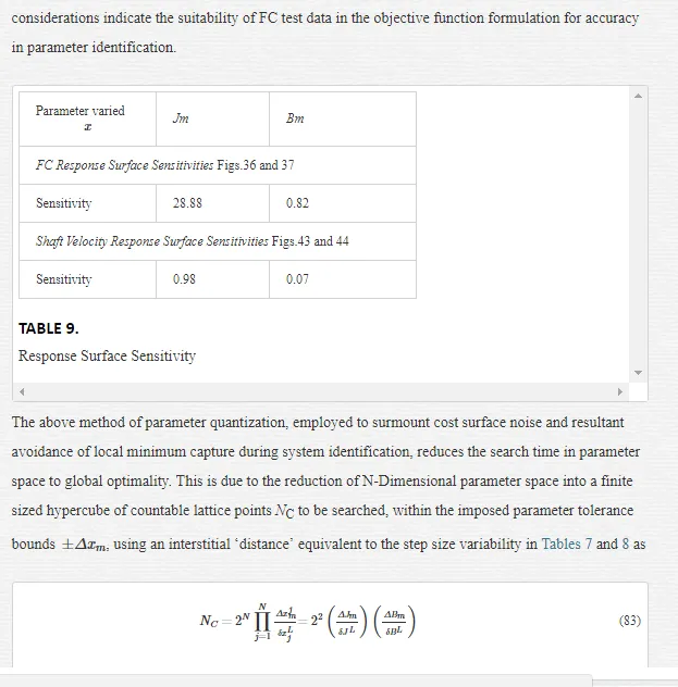
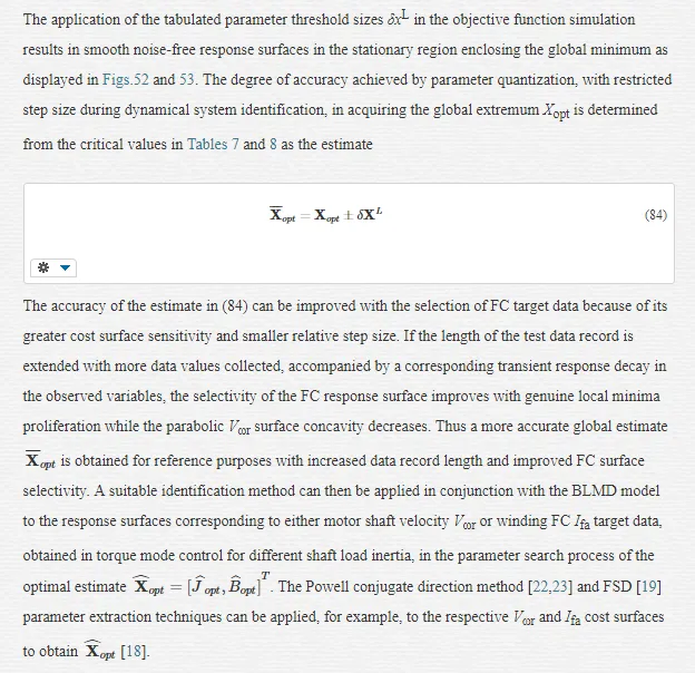
The statistical considerations of pulsed energy delivery by the PWM inverter in [18], arising from BLMD simulation with a fixed time step size, illuminates the origin of computation ‘noisiness’ and its subsequent manifestation as cost surface roughness as shown in Figs.36 and 37. For fixed shaft load inertia changes, encountered in motive power applications and electric vehicles, the use of a coarse quantization step size δJ in the inertial parameter variable about the nominal value Jm results in smooth generated and noise-free response surfaces as shown in Figs.1 and 2 for actual FC and shaft velocity target data. However for a sufficiently small step size variation in the inertia Jm and damping Bm a ‘noisy’ cost surface with a proliferation of local minima results in both cases as shown in Figs 36 and 37 for corresponding target test data. The degree of resolution of the parameter step size, that can be obtained and then used in an identification search strategy, depends upon the onset of cost surface irregularity.
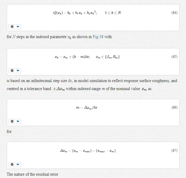
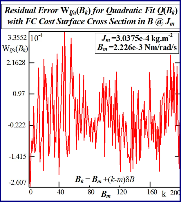
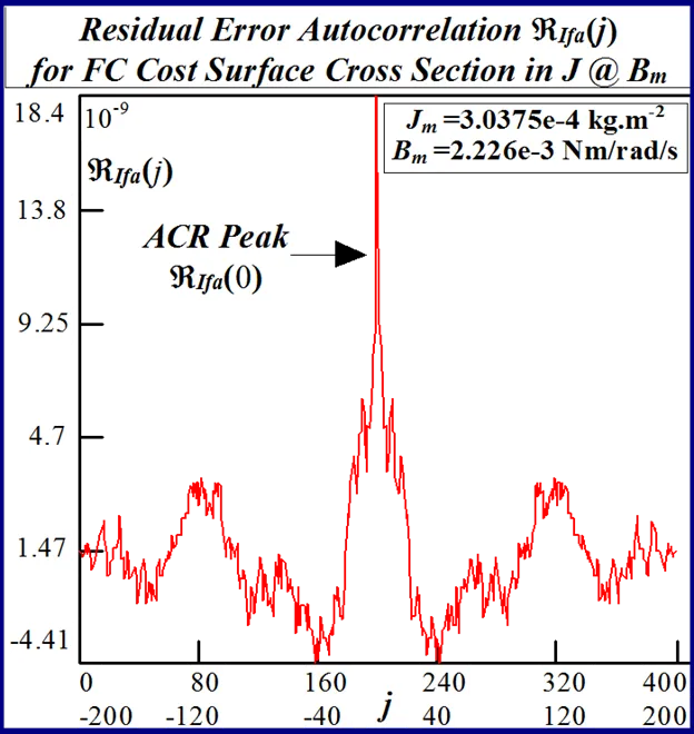
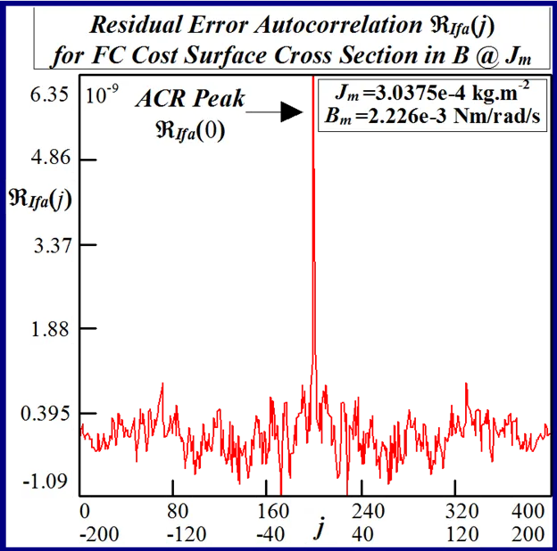
NOVEL MATHEMATICAL ANALYSIS OF QUADRATIC CURVE FITTING TO NOISY MSE COST SURFACE [18,21]
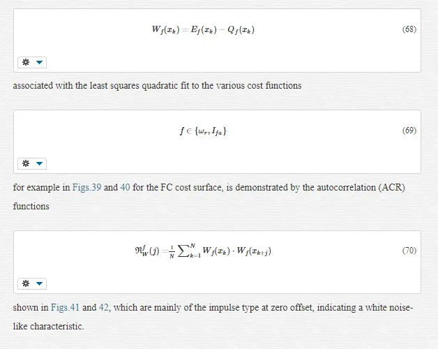
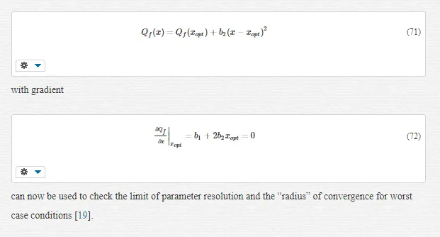
The accuracy of any classical identification scheme used in terms of parameter resolving capabilities can be gauged by fitting a quadratic [26] to the response surfaces in each test case and determining rms deviation of the PWM computation noise related residuals. The quadratic fit employed
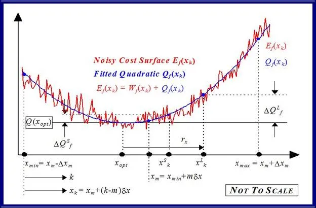
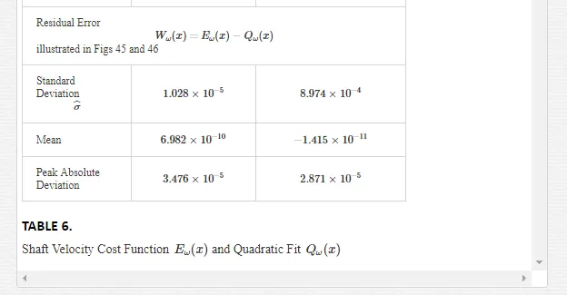
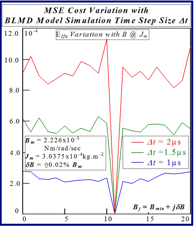
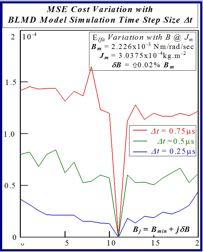
The effect of lowering the drive model simulation time step Δt, as shown in Figs. 49 and 50 for very small parameter variation in the vicinity of the global singularity, translates into a reduction of the MSE as well as gradual removal of response surface roughness. This tangible decrease in surface roughness with time step size, evident form Fig.51, is measured in terms of the standard deviation of the residual errors associated with various quadratic polynomials fitted to each of the FC cost sections. However the computational effort in terms of CPU time increases in proportion with the decrease in time step size for a given simulation trace length. The requirement for surface noise reduction with the elimination of false local minima plurality has to be balanced with a tradeoff in simulation run time in an attempt to reduce computation costs where BLMD model tractability is an issue in parameter identification and as a simulator in practical applications for performance related prediction of proposed embedded drive systems. A Taylor series expansion of the quadratic fit about the parabolic vertex
As
Conclusions
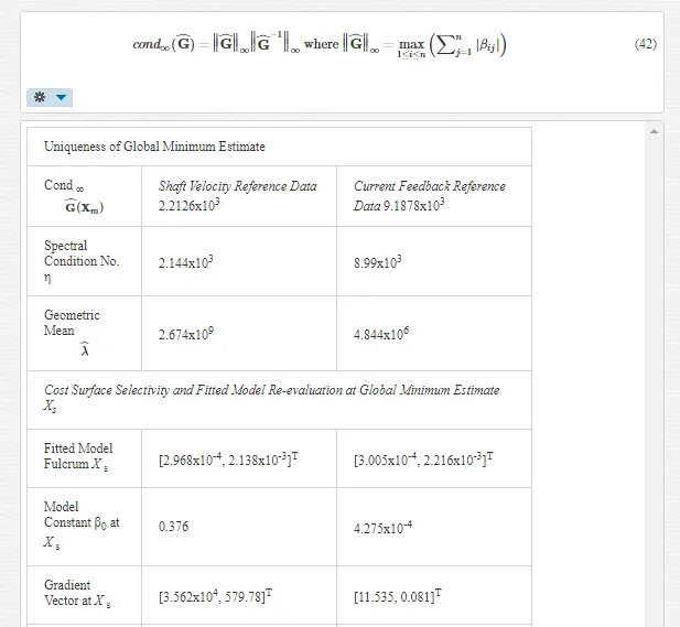
Response surface simulation has been theoretically investigated and shown to be a useful graphical tool in motor parameter identification with a multiminima objective function and BLMD model validation for electric vehicle systems. This visual concept provides an intuitive insight into the topographical structure of the cost function to be minimized, the location of the global minimum, and the relevant identification search strategy to be adopted in parameter space to obtain an accurate estimate. It also provides an alternative parameter measurement strategy against which the accuracy of other parameter identification search techniques can be judged. A novel mathematical analysis of the competing shaft velocity and current feedback response surfaces, for identification purposes, has revealed the existence of a ‘line’ minimum of possible solutions principally in the B-parameter direction via a comparison of the eigenvalues derived from the quadratic model fit of the global stationary region. This analysis also shows that the global stationary region is closed and bounded by elliptical shaped MSE contours, which guarantees the existence of an optimal parameter vector solution. Furthermore a comparison of the quadratic model eigenvalues, for the competing cost surfaces, illustrates the dominance of the current feedback response selectivity and its acceptance as the most suitable objective function during SI for accurate parameter extraction.
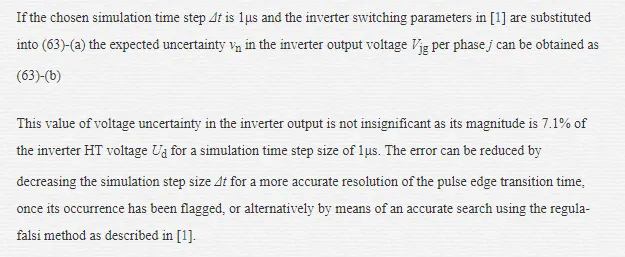
The quantization of parameter space to remove ‘false’ local minima proliferation has been examined and demonstrated to be effective in surmounting cost surface ‘noisiness’ engendered during BLMD simulation, with a finite step size, of the PWM natural sampling process. A probability analysis has shown that the error incurred in resolution of PWM edge transition times during BLMD simulation, which is responsible for cost surface granularity, is dependent on the step size and is manifested as a random error voltage at the PWM inverter output. The effect of cost surface selectivity with choice of target data in MSE penalty cost function formulation, for usage in BLMD parameter identification, has been examined with motor current feedback being the preferred option.