Nowadays, environmental issues and energy crisis relating to oil supply, pollution, and green house effects justify the need for developing of new technologies for transportation. Fuel cells as a promising technology, which provide electrical power with high efficiency, less noise, and near zero emissions compared with conventional internal combustion engines, are expected to become a viable solution for transportation applications [1, 2]. Due to its lower operating temperature and higher efficiency, a proton exchange membrane fuel cell (PEMFC) is considered as one of the most prime candidates for the vehicular applications [3–5].
In recent years, several research efforts have been carried out to develop the locomotives and the tramways powered by the PEMFC in order to encourage hydrogen economy development and reduce dependence on fossil fuels [6–12]. The locomotives and the tramways powered by the PEMFC and the energy storage system (ESS) contrasted with the diesel-electric and catenary-electric types have many advantages, which show great extensive application potential. The PEMFC exhibits good power capability during steady-state operation, but its response limitation for transient peak power demand has restrained the PEMFC from being used in large-scale and high-power transportation applications, and the lifetime of the PEMFC may be dramatically impacted by the rapid power demand variations. Due to the unidirectional power flow characteristics of the PEMFC, the energy from regenerative braking of a vehicle cannot be handled by the PEMFC. Hence, hybridizing the PEMFC with the ESS, such as battery, supercapacitor (SC), or a combination of both, can meet the total power demand and reduce the effect of drawback from the powertrain driven by stand-alone PEMFC. The hybrid tramway composed of multiple motor and trailer units, such as the type of two motor units and one trailer unit, is driven by multiple PEMFC and ESS based on the requirement of the power level and the mounting space. In order to fulfill the power balance between the load power demand and the power sources, the energy flows are distributed by the energy management system, which determines the power generation split at each sampling time between the PEMFC and the ESS, such as battery and SC.
Recently, the development of energy management system has become a topic of interest for researchers. Jia et al. [4] have presented the electrical characteristic of a hybrid power supply system combining PEMFC and SC and have investigated on the platform of an electric bicycle to improve the system efficiency. Xu et al. [5] have proposed a multimode real-time control strategy based on three typical processes of the fuel cell system for a fuel cell electric vehicle, taking the fuel economy and system durability into consideration. Li et al. [6, 7] have proposed a power sharing strategy for an energy management system of hybrid tramway and also have presented a state machine strategy based on droop control to coordinate multiple power sources of hybrid tramway. García et al. [10] have presented an equivalent consumption minimization strategy for the energy management system of the fuel cell/battery/SC tramway. Torreglosa et al. [11] have optimized the tramway hydrogen consumption based on fuel cell/battery hybrid system by the equivalent consumption minimization strategy. Fernandez et al. [12] have utilized a state machine control to satisfy the power demand from the real driving cycle for the fuel cell/battery hybrid tramway. Thounthong et al. [13] have fulfilled the comparisons between linear proportional integral and nonlinear flatness-based controllers for DC link stabilization. Eren et al. [14] have proposed a fuzzy logic supervisory controller-based power management strategy that secures the power balance in hybrid structure, enhances the FC performance, and minimizes the power losses for an FC/UC hybrid vehicular power system.
In this chapter, a hybrid propulsion system including two PEMFC systems, two batteries, and two SCs is developed for the tramway with two motor units and one trailer unit. The PEMFC systems act as main power source of tramway, and the Li-ion batteries and the SCs are utilized as the ESS to supplement the PEMFC output power during tramway acceleration and cruise and are also utilized for energy recovery during braking. A hybrid system model of tramway is established with commercially available devices. Furthermore, three energy management strategies included a fuzzy logic control (FLC), an equivalent consumption minimization strategy (ECMS) and a state machine strategy based on droop control (SMS-DC) are utilized to coordinate and distribute the power demand from each power source of the tramway, and the comparisons are also carried out to verify the validity according to a driving cycle.
Configuration of hybrid tramway
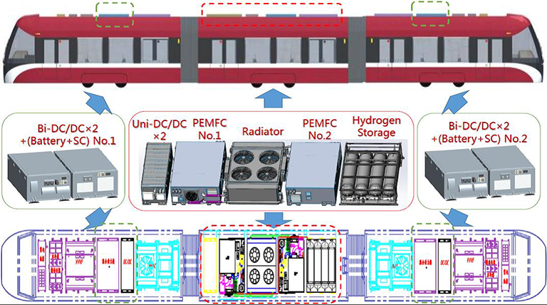
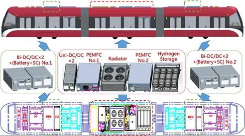
A hybrid tramway without grid connection called LF-LRV is being developed by Chinese manufacturer of Tangshan Railway Vehicle Co. Ltd and Southwest Jiaotong University. This hybrid tramway, which presents a capacity of 360 passengers and reaches a maximum speed of 77 km/h, is composed of two motor units and one trailer unit. Two motor units are supplied by the tramway traction system via an inverter box. The proposed configuration of PEMFC–battery–SC powered hybrid tramway is shown in Figure 1. The hybrid powertrain is composed of the PEMFCs (manufactured by Ballard), the batteries (manufactured by Microvast Power), the SCs (manufactured by Maxwell), the unidirectional DC/DC converters, the bidirectional DC/DC converters, the traction motors, auxiliary service module, and braking resistor. The PEMFC systems (No. 1 and No. 2) and two unidirectional DC/DC converters are placed on the trailer unit. The batteries and the SCs (No. 1 and No. 2) and two bidirectional DC/DC converters are, respectively, placed on two motor units. The boost-type unidirectional DC/DC converters are used to raise the DC voltage to 750 V. Two batteries and two SCs are connected to the traction DC bus through two bidirectional DC/DC converters, respectively, which allow the charge and discharge of the batteries and the SCs. Particularly, two SCs are utilized to consume the peak power that neither the PEMFCs nor the batteries can store because of their high specific power and high dynamic response.
Modeling of hybrid power system
MODELING OF PEMFC POWER UNIT
A PEMFC power unit, which consists of a power module subsystem, a control subsystem, and a hydrogen storage subsystem, is considered as the heart of the hybrid power system for the tramway [6, 8]. The PEMFC power unit is setup in the clean energy laboratory of Southwest Jiaotong University. In the designed PEMFC power unit, a Ballard Stack HD6 Module-FCvelocity™ is used as the PEMFC stack module. This stack module is rated at 150 kW gross power, which contains the auxiliary components for hydrogen recirculation and purge, and air humidification. The key component for the air delivery module is the air compressor, which utilizes a turbo charger manufactured by ROTREX™ Corporation. The cooling module is fulfilled with two separate cooling loops. The primary cooling loop provides heat rejection for the HD6 Module. The second cooling subsystem provides heat rejection for the PEMFC stack module condenser to ensure enough process water available at all times for air humidification.
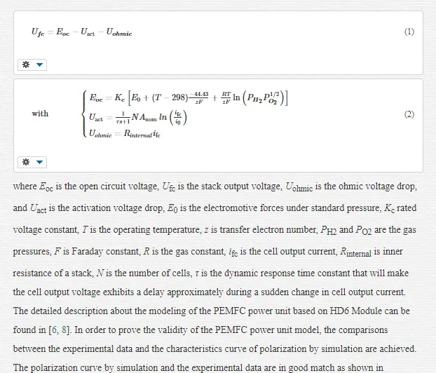
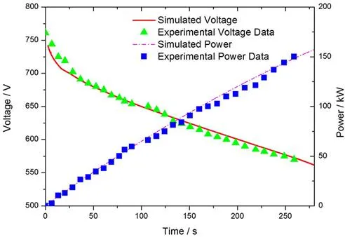
A model of PEMFC power unit is developed based on the 150 kW Ballard HD6 Module testing data. A set of assumptions generally undertaken in similar studies is carried out to focus on the dynamic response analysis for the HD6 Module requested current and output voltage [15–19]. The PEMFC output voltage is decreased from its equilibrium potential because of irreversible losses. Particularly, the concentration losses are neglected under practical working condition. The output voltage equation is expressed as
MODELING OF ENERGY STORE SYSTEM
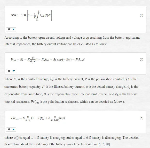
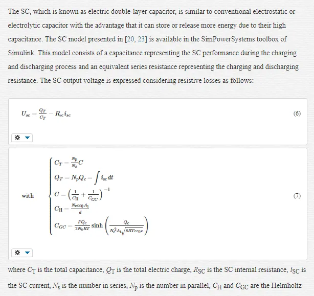
The batteries considered for the hybrid system are of type Li-ion as they have proven to exhibit high energy density and efficiency and a large number of charge/discharge cycles compared with other battery types [6, 7, 10]. The Li-ion batteries are utilized both for supplying a portion of the base load together with PEMFC and capturing the braking energy together with the SC. The behavior of this battery is represented by a modified Shepherd curve-fitting model presented in [10, 20], which is available in the SimPowerSystems toolbox of Simulink. In this model, a voltage polarization is added to the battery discharge voltage expression to better represent the effect of the battery stage of charge (SOC) on the battery performance. The validity of this model has been verified by experimental studies [20–22]. The battery SOC is calculated as follows:
MODELING OF DC/DC CONVERTERS
A power electronic device is composed of a PWM-based DC/DC converter for each power source, which connects the sources with the DC bus. The PEMFC, battery, and SC present a lower terminal voltage than the DC voltage necessary to feed the traction inverter. Two unidirectional boost DC/DC converters have been developed by using the two-quadrant chopper models included in SimPowerSystems of Simulink [24, 25]. These converter connects two PEMFC systems with the 750VDC bus maintaining the PEMFC systems stable despite variations in load. Two bidirectional converters are, respectively, utilized to the batteries and the SCs with boost operation if discharging and buck operation if charging. These converter models also been developed by using the two-quadrant chopper models included in SimPowerSystems [24, 25]. The batteries and the SCs are located on the low-voltage side, and the high-voltage side is connected to the 750VDC bus. Therefore, the effective control of the duty cycle of the bidirectional converters assure the rated voltage of the DC bus and the charge and discharge safety of the batteries and the SCs.
Energy management strategies for hybrid tramway
A STATE MACHINE STRATEGY BASED ON DROOP CONTROL
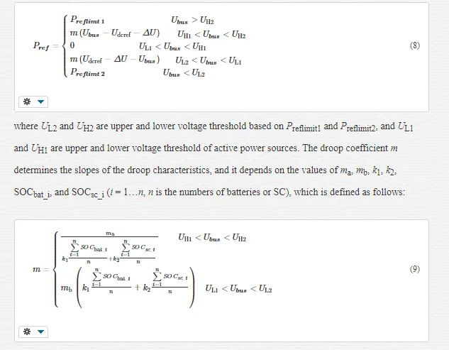
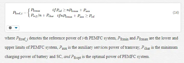
A droop control approach is presented to coordinate multiple motor and trailer units (multiple power sources), which is responsible for determining the reference power command to match the load requests from a driving cycle of tramway [7]. A reference power Pref versus bus voltage Ubus droop is adopted. This characteristic is designed to convert the external command voltage Udcref = 750 V into the reference power Pref. The larger is the amount of reference power that is injected or absorbed, the lower of the bus voltage is allowed to sag compared to the external request. Conversely, Pref is allowed to swell as the power is injected or absorbed. This correction successfully limits the circulating currents because it limits the power injections or absorptions to achieve the adjusted voltages. It is responsible for modifying the value of the bus voltage. The droop characteristic is realized by multiplying the droop coefficient m with the voltage error for the reference power, which is expressed as follows:
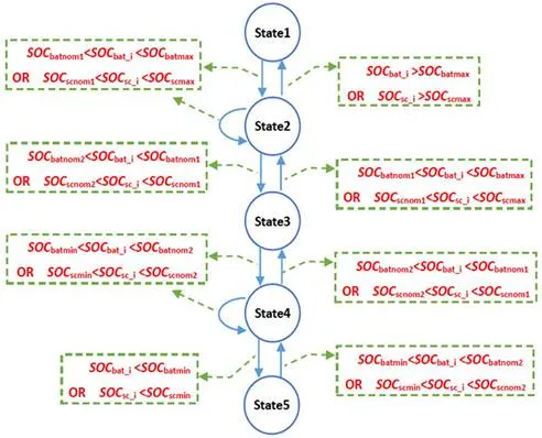
 Furthermore, the state machine strategy based on droop control (SMS-DC) is developed for the hybrid tramway. The aim of the SMS-DC is to decide the PEMFC reference power with the state change. Five states designed by the SMS are defined to distribute the reference power signals Pfcref, Pbatref, and Pscref for the PEMFC, the battery and the SC through regulating two unidirectional DC/DC converters, and four bidirectional DC/DC converters. SOCbatmin and SOCbatmax are the lower and the upper limits of battery SOC; SOCscmin and SOCscmax are the lower and the upper limits of SC SOC; SOCbatnom1and SOCbatnom2 are the upper and lower bounds of the preferred zone of battery SOC; and SOCscnom1and SOCscnom2 are the upper and lower bounds of the preferred zone of SC SOC. And also, the SOC levels of batteries and SCs are divided into the high SOC, normal SOC and low SOC, and the changes between these levels are performed by means of two hysteresis cycles. The state chart diagram of the SMS is described as Figure 3 shown. The PEMFC reference power Pfcref is determined based on the batteries and SCs SOC range and the reference power derived from droop control. In addition, the reference signal is decided for energy dissipation via the braking resistor if required during regenerative braking. These states are defined as follows:

ENERGY MANAGEMENT STRATEGY BASED ON FUZZY LOGIC CONTROL
The fuzzy logic controller (FLC) is more appropriate for the energy management system of hybrid tramway. A list of IF-THEN rules is adopted to describe input and output relationship of the controller [6]. In the fuzzy inference system, two decentralized FLC are designed improve the efficiencies of tramway and PEMFC systems on condition that dynamic property of tramway is satisfied.
The No. 1 FLC (FLC1) has three input variables and one output variable. The input variables include the demand power of electrical motor Pm1, the battery SOC, and the SC bank SOC (CSOC). The PEMFC reference power Pref1 is defined as the output variable. The No. 2 FLC (FLC2) has three input variables and one output variable. The surplus demand power of motor Pm2, and the battery SOC and the SC CSOC are defined as the input variables. The SC reference power Pref3 is defined as the output variable. The form of fuzzy reasoning is “IF Pm1 is Ai AND SOC is Bi AND CSOC is Ci, Then Pref1 is Di”. Mamdani inference method is adopted to implement the fuzzy reasoning. More detailed description about the energy management strategy based on fuzzy logic control can be found in [6].
EQUIVALENT CONSUMPTION MINIMIZATION STRATEGY
In the present hybrid tramway, if the batteries or the SCs supply electrical energy, their SOC decreases, so that the batteries or the SCs will need to be recharged by the energy proceeded from two PEMFC systems or the tramway braking in order to maintain a desired SOC. Hence, extra hydrogen consumption could be needed due to the energy obtained from the tramway braking is generally insufficient. If the batteries or the SCs is recharged their SOC increases and the energy will supply to the tramway in future accelerations or start-ups resulting in a reduction of the hydrogen consumption. The electrical energy consumption of the batteries and the SCs are transformed into an equivalent hydrogen consumption to make the two comparable [10].
The equivalent consumption minimization strategy (ECMS) focuses on minimizing the equivalent hydrogen consumption of the hybrid powertrain C (g), which is calculated as sum of two PEMFC systems hydrogen consumption Cfc, and two batteries and two SCs-equivalent hydrogen consumptions, Cbat and Csc. In this work, the mathematical problem used to optimize the equivalent hydrogen consumption is formulated as follows:
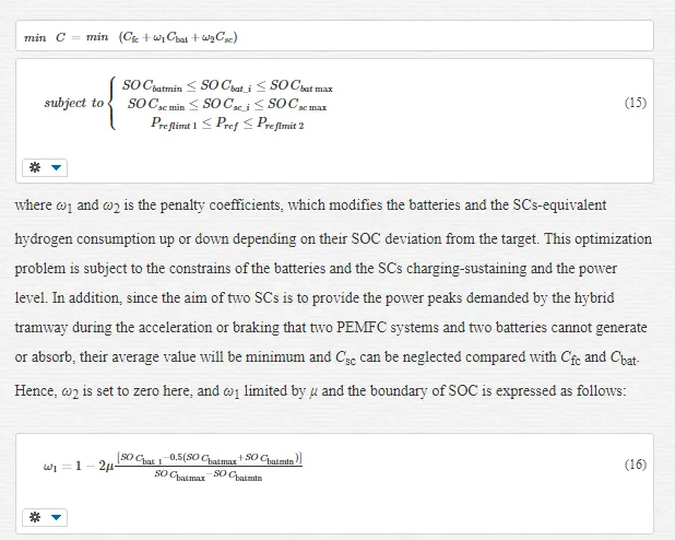
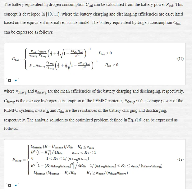
where Pbatopt is the optimized power of the battery, and Ubatmin and Ubatmax are the minimal and the maximal allowed battery voltages, respectively. K1, xmin, and xmax are defined variables. In addition, since the aim of two SCs is to provide the power peaks demanded by the hybrid tramway during the acceleration or braking that two PEMFC systems and two batteries cannot generate or absorb, their average value will be minimum and Csc can be neglected compared with Cfc and Cbat.
Results and discussions
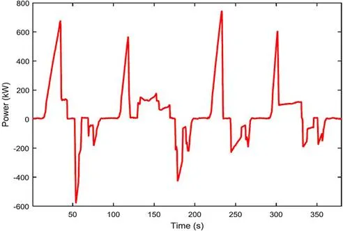
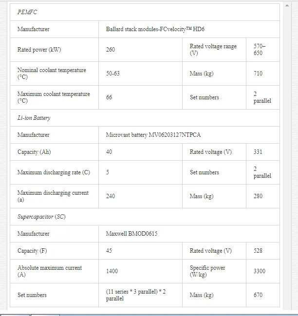
A real driving cycle of the tramway from Samsun in Turkey is adopted to evaluate the performance of these energy management strategies for the hybrid system. A round-trip route, which consists of a symmetrical route of going and return, has been adopted as shown in Figure 4. The hybrid propulsion system of tramway is composed of commercial devices, such as Ballard FCvelocity™ HD6, Microvast Battery MV06203127NTPCA, and Maxwell BMOD0615. The premises are considered carefully for the hybrid system sizing. The maximum power of two PEMFC systems should be higher than the average power demanded by the tramway during the driving cycle in order to avoid excessive SOC drop of the batteries and the SCs. A hybrid propulsion system considered for the tramway presents two PEMFC systems (300 kW), two Li-ion batteries (40 Ah), and two SC banks (45 F). These devices have been selected from commercially available components as Table 1 shown.
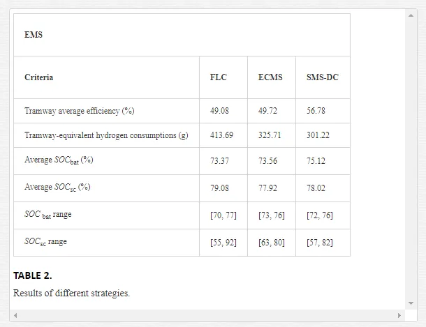
The performance comparison of these energy management strategies are carried out under the same the driving cycle and hybrid topology. In Table 2, the criteria for performance comparison are the average efficiency and equivalent hydrogen consumptions of tramway, the average value of SOCbat and SOCsc, and the variation range of SOCbat and SOCsc. Compared with the other strategies, the SMS-DC provides better tramway average efficiency (56.78%) and the tramway-equivalent hydrogen consumptions (301.22 g). The maximum difference obtained between the best and the worst tramway average efficiency is 7.7%. The efficient use of the batteries and SCs energy (average SOC of 75.12 and 78.02%) are also achieved by the SMS-DC because the final average SOC value of batteries and SCs are closer to the initial value. The best results related to the variation ranges of SOCbat and SOCsc are obtained by the ECMS, but at the expense of lower overall efficiency (49.72%).
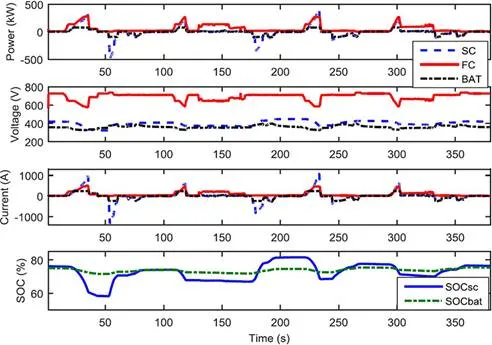
As the results of the energy management system based on the SMS-DC, the output power, voltage, current, and SOC of different power sources are given in Figure 5, respectively. With regard to the output power, the PEMFC systems only increase or decrease the power during high accelerations or brakings. It can be observed that the proposed SMS based on droop control is able to guarantee the stable operation of the PEMFC systems during the most of the drive cycle. The output power of the batteries alternates between negative and positive according to charging or discharging. It helps provide a portion of the positive low-frequency components of power demand to reduce the burden of the PEMFC and absorb the slow-variation negative portion. Additionally, due to the PEMFC dynamic limitation, the SCs provide the transient power demand successfully during sudden acceleration or braking. Their fast response fulfill the power demand, increase the hybrid system power density, and have to generate or absorb the power, which, either the PEMFC or the battery, are not able to generate or absorb.
Conclusions
In this chapter, the energy management system for the hybrid tramway based on multiple PEMFC systems, batteries, and SCs is designed without grid connection. The hybrid propulsion system model is developed with commercially available devices. The FLC, the ECMS, and the SMS-DC are utilized to coordinate and distribute the power demand to each power source appropriately, avoid the transients and rapid changes of power demand, and achieve high efficiency. According to the driving cycle of the tramway, the testing of the energy management systems is carried out. The comparisons with the FLC, the ECMS, and the SMS-DC verify that the higher average efficiencies of the tramway, the lower tramway-equivalent hydrogen consumptions, and more efficient use of the batteries and SCs energy are achieved by the SMS-DC. Hence, the suitable designed energy management system for the hybrid tramway will enhance the hydrogen consumptions of overall hybrid system and the efficiencies of each power source.