Although the history of diesel engines extends back to the end of the nineteenth century and in spite of the predominant position such engines now hold in various applications, they are still subject of intensive research and development. Economic pressure, safety critical aspects, compulsory onboard diagnosis as well as the reduction of emission limits lead to continuous advances in the development of combustion engines.
Condition monitoring and fault diagnosis represent a valuable set of methods designed to ensure that the engine stays in good condition during its lifecycle, [7] and [13]. Diagnosis in the context of diesel engines is not new and various approaches have been proposed in the past years, however, recent technical and computational advances and environmental legislation have stimulated the development of more efficient and robust techniques. In addition, the number of electronic components such as sensors or actuators and the complexity of engine control units (ECUs) are steadily increasing. Meanwhile, most of the software running on the main ECU is responsible for condition monitoring of sensor signals, monitoring parameter ranges, detecting short/open circuits, and verifying control deviations. However, these kinds of condition monitoring systems (CMS) are not designed to detect and clearly identify different engine failures, sensor drifts and to predict developing failures, i.e. to asses degradation of certain components right in time. Especially the reliable detection and separation of engine malfunctions is of major importance in various fields of industry in order to predict and to plan maintenance intervals.
Diesel engines usually consist of a fuel injection system, pistons, rings, liners, an inlet and exhaust system, heat exchangers, a lubrication system, bearings and an ECU. For the design of an efficient CMS it is essential to know as much as possible about the underlying thermodynamical processes and possible faults and malfunctions. This information can be seen as a-priori knowledge and can be used to increase the robustness of fault detection algorithms.

In the following, common diesel engine faults and fault mechanisms, and their causes are listed.
• power loss caused by misfire and blow-by.
• emission change caused by loss of compression, turbocharger malfunction, blocked fuel filter, incorrect injector timing, poor diesel fuel, incorrect fuel air ratio, air intake filter blocked, incorrect piston topping, or ECU malfunction etc.
• lubricating system fault due to incorrect oil pressure and oil deterioration
• thermal overload as a result of one or a combination of leaking injection valves, piston ring-cylinder wear or failure, eroded injector holes, too low injection pressure, high engine friction, misfire, leaking intake or exhaust manifold/valves, high coolant or lubricant temperature etc.
• leaks in the fuel injection system, lubrication system, or air intake
• wear of the piston caused by either corrosion or abrasion, or both
• noise and vibration caused by the impact of one engine part against another (mechanical noise), vibrations resulting from combustion, intake and exhaust noise
• other faults like knocking, filter faults, fuel contamination and aeration
The main challenge in engine fault detection is the ambiguity between faults and causes. Certain engine faults may be caused by a combination of causes (with different weightage). The assessment of engine states from sparse measurement data as well as a reliable assignment of failure effects and causes are an active research field. The problems relating to marine diesel engines, especially medium- and high-speed engines, are due mainly to their large size and their high operating speed. Occurring faults of marine diesel engines which are on the high seas for several months may lead to expensive holding times. On the other hand, additional sensors and measurement equipment for condition monitoring are usually undesirable since engines have to be modified to place those additional sensors. Such additional sensors are e.g. viscosity sensors to sense oil degradation as described by [12] and [1], or acoustical sensors to determine faults based on acoustical pressure and vibration signals measurements as can be found in [5], [11], and [2].
A topical review on different fault diagnosis methods for condition monitoring can be found in [7]. Both standard methods (Fourier analysis of pressure, torque, power, crankshaft speed and vibration signals) and advanced methods (neural networks, fuzzy techniques) are encountered and briefly described. [14] discuss the detection of a single fault in a statistical framework (hypotheses testing) by measuring acoustic emission energy signals and applying an independent component analysis. However, most methods usually rely on heuristic knowledge and on a data training phase as well as on the specification of threshold levels in order to assign states as faulty or non-faulty. Since the last decade, a paradigm shift from classical signal processing and feature extraction to computationally expensive model-based CMS can be observed. In contrast to classical condition monitoring, model-based methods can manage distributed and multiple correlated parameters, as described by [16] and [13]. They cover a wide variety of states since the engine behavior is described in terms of physical relationships and hence, parameters that influence certain parts of the first principles equations can be isolated or at least correlations can be determined. Three different methods to estimate the compression ratio from simulated cylinder pressure traces are presented in [8]
and compared in terms of estimation accuracy and computation time. By reconstructing only one single failure based on polytropic compression and expansion of the cylinder pressure significant results have been reported. However, the detection of multiple failures from in-cylinder pressure measurements is still an open issue. Different Fuzzy-based methods also provide remarkable results for detecting only one single fault such as in [3], [4], [17], and [18].
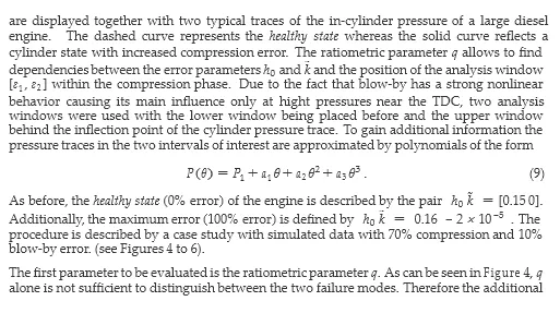
In this work the main focus is on a robust model-based identification and separation of two common failure modes of large marine diesel engines by accurately modeling the underlying thermodynamic process. These two failures, which cause very similar changes in the cylinder pressure, are
• changes in the compression ratio primarily leading to emission and power changes
• increased blow-by mainly resulting in a loss of power.
Following a model-based approach, it is possible to identify the above mentioned failures and to clearly separate them given uncertain measurement data with low sampling rate (1◦ of crank angle). By measuring only cylinder pressure traces of every cylinder, the symptoms due to faults are determined, [8]. Two different approaches – ratiometric and nonlinear parameter estimation – are investigated, validated with measured data and compared to each other in terms of performance, accuracy, and robustness given sensor drift and uncertain measurements, [15].
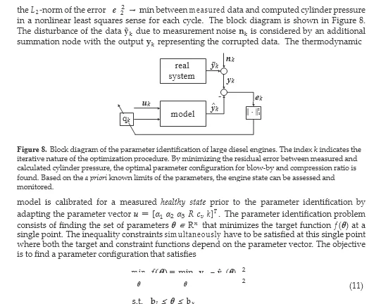
The thermodynamical process model
Various approaches to model diesel engines have been proposed in literature, however, the main focus is on small-size engines that are commonly used in the automotive industry. The typical differential equations that represent the thermodynamic processes, i.e. the interrelationship between system pressure, temperature and mass can be found in [6], [9], and [10].
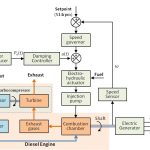
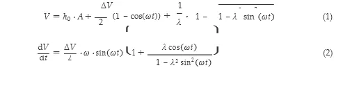
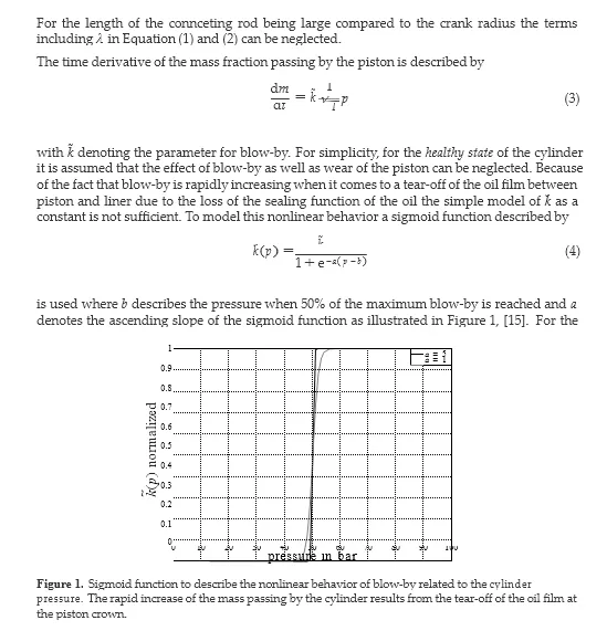
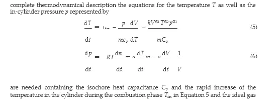
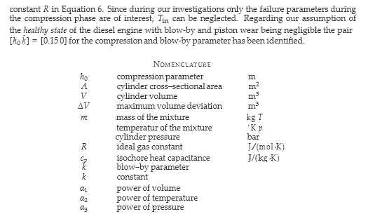
Since in this work, identification of blow-by and compression ratio is of primary interest, a simplified thermodynamical model capable of running in real-time is developed. Note that a list of symbols used in the following equations is given at the end of this chapter. The main reason for compression losses are referred to as damages of the piston crown during the combustion phase leading up to an increasing volume V0 in the top dead center (TDC) of the piston. In the equation for the volume V in the cylinder the constant volume fraction V0 is represented by the term h0 · A with h0 being the compression parameter and A the cross-sectional area of the cylinder. In the time-varying fraction of the volume equation ω denotes the instantaneous angular velocity of the crankshaft and ΔV the maximum volume deviation related to the movement of the piston. By also taking into account the ratio λ of the crank radius to the length of the connecting rod regarding to the equation of a standard crank mechanism the equation for the volume and its time derivative can be summarized as follows
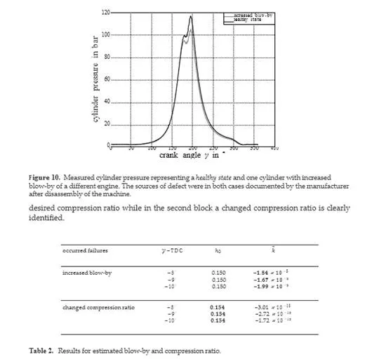
The blow-by estimate remains very small denoting that blow-by has not increased. In addition, the nonlinear approach exhibits a robust parameter estimation behavior given uncertainties in TDC within a certain range.
Conclusions
This book chapter addresses different methods for robust detection of increased blow-by and compression faults from measured cylinder pressure traces of large marine diesel engines. By modeling the underlying thermodynamic process, including prior knowledge about the system, and characterizing the measurement noise, faults can be detected and isolated from each other even in the presence of sensor drift.
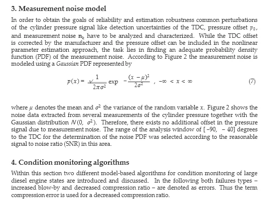
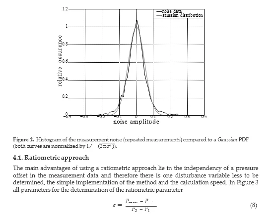
The ratiometric approach allows only qualitative statements and can not clearly distinguish between the two failure modes blow-by and compression losses. The main drawbacks of
the algorithm are its sensitivity to measurement noise and the fact that crank angles close to the TDC are required to see a proper curvature in the ratio of the pressure. On the other hand, the method is very fast due to its simplicity and independent to a pressure offset in the measurement signal. In contrast, the nonlinear parameter estimation methodology features higher accuracy in estimation results and allows to distinguish between certain types of faults, however, introducing a greater modeling effort and computational costs.
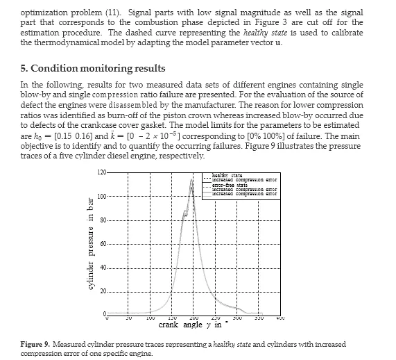
The applicability of the model-based approaches is verified by measurement data given information about the sources of defect of the engine. Due to the low sampling interval of 1◦ of the crank angle the condition monitoring system (CMS) exhibits real-time performance. The robustness is investigated by analyzing the statistics of the estimated parameters of blow-by and compression ratio. Furthermore, the influence of the upper limit of the analysis window close to the TDC is examined. The detection of these failures can be used in order to predict maintenance intervals. Based on cylinder pressure traces the proposed methods feature the applicability to other domains including large trucks, rail vehicles, and stationary power stations.