The basic goals of the automotive industry; a high power, low specific fuel consumption, low emissions, low noise and better drive comfort. With increasing the vehicle number, the role of the vehicles in air pollution has been increasing significantly day by day. The environment protection agencies have drawn down the emission limits annually. Furthermore, continuously increasing price of the fuel necessitates improving the engine efficiency. Since the engines with carburetor do not hold the air fuel ratio close to the stoichiometric at different working conditions, catalytic converter cannot be used in these engines. Therefore these engines have high emission values and low efficiency. Electronic controlled Port Fuel Injection (PFI) systems instead of fuel system with carburetor have been used since 1980’s. In fuel injection systems, induced air can be metered precisely and the fuel is injected in the manifold to air amount. By using the lambda sensor in exhaust system, air/fuel ratio is held of stable value. Fuel systems without electronic controlled it is impossible to comply with the increasingly emissions legislation.
If port fuel injection system is compared with carburetor system, it is seen that has some advantages. These are;
1. Lower exhaust emissions.
2. Increased volumetric efficiency and therefore increased output power and torque.
The carburetor venturi prevents air and, in turn, volumetric efficiency decrease.
3. Low specific fuel consumption. In the engine with carburetor, fuel cannot be delivered the same amount and the same air/fuel ratio per cycle, for each cylinder.
4. The more rapid engine response to changes in throttle position. This increases the drive comfort.
5. For less rotation components in fuel injection system, the noise decreases
(Heywood, 2000; Ferguson, 1986).
Though the port fuel injection system has some advantages, it cannot be meet continuously increased the demands about performance, emission legislation and fuel economy, at the present day (Stone, 1999). The electronic controlled gasoline direct injection systems were started to be used instead of port fuel injection system since 1990’s.
The Gasoline Direct Injection (GDI) engines give a number of features, which could not be realized with port injected engines: avoiding fuel wall film in the manifold, improved accuracy of air/fuel ratio during dynamics, reducing throttling losses of the gas exchange by stratified and homogeneous lean operation, higher thermal efficiency by stratified operation and increased compression ratio, decreasing the fuel consumption and CO2 emissions, lower heat losses, fast heating of the catalyst by injection during the gas expansion phase, increased performance and volumetric efficiency due to cooling of air charge, better cold- start performance and better the drive comfort (Zhao et al., 1999; Karamangil, 2004; Smith et al., 2006).
The Performance and Exhaust Emissions of The Gasoline Direct Injection
(GDI) Engine
Performance of the GDI Engine
The parameters that have the greatest influence on engine efficiency are compression ratio and air/fuel ratio. The effect of raising compression ratio is to increase the power output and to reduce the fuel consumption. The maximum efficiency (or minimum specific fuel consumption) occurs with a mixture that is weaker than stoichiometric (Çelik, 2007). Because the port fuel injection engines work at stoichiometric air/fuel ratio, it is impossible to see more improvement in the fuel economy. In these engines, the compression ratio is about 9/1-10/1. To prevent the knock, the compression ratio cannot be increased more. For the same engine volume, the increasing volumetric efficiency also raises the engine power output.
GDI engine operate with lean mixture and unthrottled at part loads, this operation provide significantly improvements in fuel economy. At full load, as the GDI engine operates with homogeneous charge and stoichiometric or slightly rich mixture, this engine gives a better power output (Spicher et al., 2000). In GDI engine, fuel is injected into cylinder before spark plug ignites at low and medium loads. At this condition, Air/Fuel (A/F) ratio in cylinder vary, that is, mixture in front of spark plug is rich, in other places is lean. In all cylinder A/F ratio is lean and A/F ratio can access until 40/1. In homogeneous operation, fuel starts injecting into cylinder at intake stroke at full loads (Alger et al., 2000; Çnar, 2001). The fuel, which is injected in the intake stoke, evaporates in the cylinder. The evaporation of the fuel cools the intake charge. The cooling effect permits higher compression ratios and increasing of the volumetric efficiency and thus higher torque is obtained (Muñoz et al., 2005). In the GDI engines, compression ratio can gain until 12/1 (Kume, 1996). The knock does not occur because only air is compressed at low and medium loads. At full load, since fuel is injected into cylinder, the charge air cool and this, in turn, decreases knock tendency.
Since the vehicles are used usually in urban traffic, studies on improving the urban driving fuel economy have increased. Engines have run usually at part loads (low and medium loads) in urban driving. Volumetric efficiency is lower at part loads, so engine effective compression ratio decreases (e.g. from 8/1 to 3/1-4/1), engine efficiency decreases and fuel consumption increases. The urban driving fuel economy of the vehicles is very high (Çelik,
1999). Distinction between the highway fuel economies of vehicles is very little. As majority
of the life time of the vehicles pass in the urban driving, the owners of the vehicles prefer the vehicles of which the urban driving fuel economy is low.
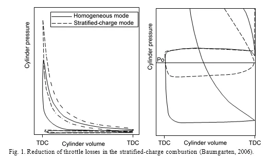
At full load, as the GDI engine operate with throttle, only a small reduction of fuel consumption can be obtained to the PFI engine. There is the more fuel economy potential at part load. At compression stroke, since air is given the cylinders without throttle for stratified charge mode, pumping losses of the GDI engine is minimum at part loads, Fig.1 (Baumgarten, 2006). The improvements in thermal efficiency have been obtained as a result of reduced pumping losses, higher compression ratios and further extension of the lean operating limit under stratified combustion conditions at low engine loads. In the DI gasoline engines, fuel consumption can be decreased by up to 20%, and a 10% power output improvement can be achieved over traditional PFI engines (Fan et al., 1999).
![]()
![]() The CO2 emissions, which are one of the gases, bring about the global warming. To decrease CO2 emitted from vehicles, it is required to decrease fuel consumption. Downsizing (reduction of the engine size) is seen as a major way of improving fuel consumption and reducing greenhouse emissions of spark ignited engines. In the same weight and size, significant decreases in CO2 emissions, more power and higher break mean effective pressure can be obtained. GDI engines are very suitable for turbocharger applications. The use of GDI engine with turbocharger provides also high engine knock resistance especially at high load and low engine speed where PFI turbocharged engines are still limited (Lecointe & Monnier, 2003; Stoffels, 2005). Turbocharged GDI engines have showed great potential to meet the contradictory targets of lower fuel consumption as well as high torque and power output (Kleeberg, 2006).
The CO2 emissions, which are one of the gases, bring about the global warming. To decrease CO2 emitted from vehicles, it is required to decrease fuel consumption. Downsizing (reduction of the engine size) is seen as a major way of improving fuel consumption and reducing greenhouse emissions of spark ignited engines. In the same weight and size, significant decreases in CO2 emissions, more power and higher break mean effective pressure can be obtained. GDI engines are very suitable for turbocharger applications. The use of GDI engine with turbocharger provides also high engine knock resistance especially at high load and low engine speed where PFI turbocharged engines are still limited (Lecointe & Monnier, 2003; Stoffels, 2005). Turbocharged GDI engines have showed great potential to meet the contradictory targets of lower fuel consumption as well as high torque and power output (Kleeberg, 2006).
In GDI engine, by using twin charging system drive comfort, engine torque and power can be increased for the same engine size. For example, Volkswagen (VW) has used the dual charging system in TSI (twin charged stratified injection) engine. The system includes a roots-type supercharger as well as a turbocharger. The supercharger is basically an air compressor. A mechanical device driven off the engine’s crankshaft, it employs rotating vanes which spin in opposite directions to compress air in the engine’s intake system. The high and constant torque is obtained at wide range speed by activate supercharger at low speeds and turbo charger at high speeds (Anon, 2006).
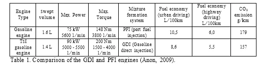
In Table 1, it is given specifications of the two different engines belonging to the 2009 model VW Passat vehicle, for example. TSI engine urban driving fuel economy is 18% lower than that of PFI engine. CO2 emission is 12% lower than that of PFI engine. Although TSI engine swept volume is lower than PFI engine, power and torque is higher by 20% and 35%, respectively (Table 1). As engine torque is maximum at interval 1500-4000 1/min, shifting is not necessary at the acceleration and thus drive comfort increase (Anon, 2009).
Exhaust Emissions of the GDI Engine
CO emission is very low in GDI engine. CO varies depending on air /fuel ratio. CO is high at rich mixtures. Since GDI engines operate with lean mixture at part loads and stoichiometric mixture at full load, CO is not a problem for these engines. In GDI engine, due to the wetting of the piston and the cylinder walls with liquid fuel, HC emission can increase. Hydrocarbon (HC) emissions are a function of engine temperature and, therefore it can rise during cold start. The cold starts characteristics vary depending on the fuel distribution characteristics, the in-cylinder air motion, fuel vaporization, and fuel-air mixing (Gandhi et al., 2006).
During cold-start of a GDI engine, homogeneous operation can be employed due to a higher exhaust gas temperature resulting in a shorter time for catalyst light-off, and lower engine out HC emissions (Gandhi et al., 2006). Gasoline engines do not emit soot emission normally. Soot emission can occur at very rich mixtures. However, the GDI engines emit soot at stratified-charge operation, as in–cylinder can be areas with very rich mixtures. In addition, in GDI engine, if mixture formation do not realize at full loads due to rich mixture, the soot emission can increase. NOx emission is maximum at high cylinder temperatures and at λ =1.1. As torque output rises, temperatures rise and, in turn, the engine-out NOx emissions display an increase. NOx emissions increase especially at full load.
The Emission Control in GDI Engine
Environmental legislation determines the limits for exhaust emissions in the spark ignition engines. It is required the treatment of the exhaust gases to meet these limits. The three-way catalytic converter show high performance for converting the CO, HC and NOx in the engines with operation at λ=1.0. But, NOx cannot be completely converted harmless gases at lean mixture operation. Therefore, engines with lean mixture also require a NOx storage type catalytic converter to convert the NOx.
The two catalytic converters are successively used in GDI engine exhaust system. The one is Pre-catalytic converter (Three Way Converter -TWC). This converter has little volume and is connected close to the engine. The other is main catalytic converter which combines a NOx catalyst and a TWC. This converter has higher volume than the pre-catalytic converter and is connected not close to the engine. The Pre-catalytic converter convert the CO, HC and NOx to harmless gases (CO2, H2O and N2) at λ=1.0. However, when engine operates at stratified mode with lean mixture, NOx cannot be converted to nitrogen. In such cases, NOx is sent to main catalytic converter (Anon, 2002).
In the NOx storage type catalytic converter, the components such as Ba and Ca are used for NOx conversion at lean mixtures. These components provide NOx to storage. At λ=1.0, the operation of the NOx converter resembles three way converter. At lean mixtures, NOx conversion is realized in three stages: NOx accumulation, NOx release and conversion. Nitrogen oxides reacts chemically with barium oxide (BaO) and thus barium nitrate (Ba(NO3)2 forms. (NOx storage stage). Then, to convert, engine is operated momentarily in the rich homogeneous mode. Thanks to rich mixture, there is CO in exhaust system. The barium nitrate reacts chemically with CO and, as a result of this CO2, BaO and NO arise (NOx release stage). And then, NO reacts chemically with CO and, N2 and CO2 form (conversion stage). NOx storage converter can storage the NOx at temperatures of 250-500C (Anon, 2002; Bauer, 2004). An exhaust gas recirculation system is necessary, as the NOx aftertreatment systems do not reach the conversion rates of λ = 1 concepts. With the exception at the highest loads, exhaust gas recirculation (EGR) is used extensively to control NOx emissions (Alkidas, 2007).
To meet the valid emission limits and diagnose the pre and main catalyst faults, and provide optimum engine operation 4 sensors (3 lambda sensor and 1 exhaust gas temperature sensor) are used in the exhaust system. The wide band lambda sensor upstream of pre-catalyst determines residual oxygen value in exhaust gas. The required λ for homogeneous lean operation can be controlled by this sensor. For each catalytic converter two lambda sensors (upstream and downstream sensor) are used. The faults of the pre and main converters can be diagnosed by signal of dual sensors. The temperature sensor is used to determine the temperature of the NOx catalyst (Küsell et al., 1999).
The Mixture Formation and Operation Modes in The GDI Engine
The Mixture Formation
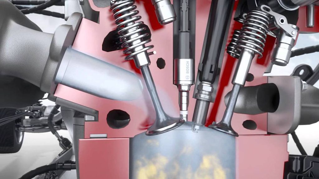
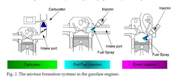
The air-fuel mixture in the gasoline engines is prepared in-cylinder and out-cylinder. While the mixture in the engine with carburetor and port fuel injection is prepared out-cylinder, mixture in the gasoline direct injection engines is prepared in-cylinder, Figure 2
Wall-Guided combustion system: The fuel is transported to the spark plug by using a specially shaped piston surface. As the fuel is injected on the piston surface, it cannot completely evaporate and, in turn, HC and CO emissions, and fuel consumption increase. To use this system alone is not efficient.
Air-Guided combustion system: The fuel is injected into air flow, which moves the fuel spray near the spark plug. The air flow is obtained by inlet ports with special shape and air speed is controlled with air baffles in the manifold. In this technique, fuel does not wet the piston and cylinder. Most of stratified-charge GDI engines use a large-scale air motion (swirl or tumble) as well as specially shaped piston a surface in order to keep the fuel spray compact and to move it to the spark plug (Baumgarten, 2006). In the air-guided and wall- guided combustion systems the injector is placed remote to the spark plug.
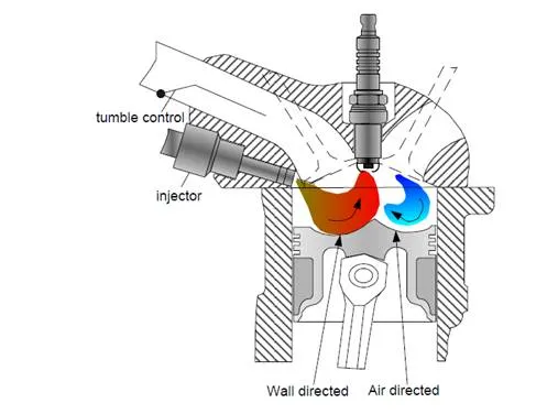
VW direct injection combustion system is a combination of two systems– wall guided and air guided –by tumble flow. This system is less sensitive against the cyclic variations of airflow. This combustion system shows advantages as well in the stratified and in the homogenous mode. Injector is intake-side placed, Fig. 5. The fuel is injected to the piston under given angle. The piston has two bowls. The fuel bowl is on the intake-side; the air bowl is on exhaust-side. Tumble flow is obtained by special shaped intake port (Stefan,
2004). The fuel is guided simultaneously via air and fuel bowl to the spark plug.
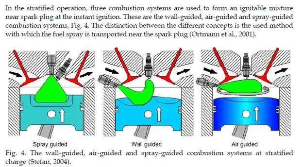
Spray-Guided combustion system: In the spray-guided technique fuel is injected near spark plug where it also evaporates. The spray-guided technique theoretically has the highest efficiency. The spray guided combustion process requires advanced injector systems such as piezo injection. This technique has some advantages: reduced wall wetting, increased stratified operation region, less sensitive to in-cylinder air flow, less sensitive to cylinder to cylinder variation and reduced raw HC emissions. Reported disadvantages are spark plug reliability (fouling) and poor robustness (high sensitivity to variation in ignition
&injection timing) (Cathcart & Railton, 2001). Mercedes-Benz developed a new spray- guided combustion system. This system has the Stratified-Charged Gasoline Injection (CGI) engine with Piezo injection technology. The spray-guided injection achieves better fuel efficiency than conventional wall-guided direct injection systems. The main advantage of the CGI engine is obtained at the stratified operating mode. During this mode the engine is run with high excess air and thus excellent fuel efficiency is provided. Multiple injections extend this lean-burn operating mode to higher rpm and load ranges, too. During each compression stroke, a series of injections is made spaced just fractions of a second apart. This allows the better mixture formation and combustion, and lower fuel consumption (Website 1, 2010).
The Operating Modes
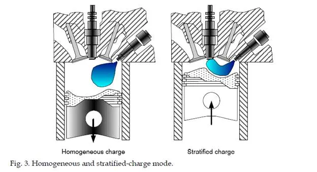
GDI engine operates at different operating modes depending on load and engine speed for a stable and efficient engine operation. These engines have three basic operating modes, stratified with an overall lean mixture, homogeneous with lean mixtures and homogeneous with stoichiometric mixtures. The engine is operated with the stratified, homogeneous lean and homogeneous stoichiometric modes; at low load and speed, at medium load and speed and at high load and speed, respectively. Fig. 6 shows an example of the GDI operating modes depending on engine load and speed.
The engine control unit continually chooses the one among the operating modes. Each mode is determined by the air-fuel ratio. The stoichiometric air-fuel ratio for petrol (gasoline) is
14.7:1 by weight, but ultra lean mode (stratified-charge) can involve ratios as high as 65:1.
These mixtures are much leaner than conventional mixtures and reduce fuel consumption considerably. Stratified-charge mode is used for light-load running conditions, at constant or low speeds, where no acceleration is required. The fuel has to be injected shortly before the ignition, so that the small amount of air-fuel mixture is optimally placed near the spark plug. This technique enables the usage of ultra lean mixtures with very high air-fuel ratio, impossible with traditional carburetors or even port fuel injection (Website 2, 2010). The lean burn increases the NOx emissions. In this mode, EGR is actuated in order to decrease NOx. The area of stratified operation is limited by load and speed. At high load, the mixture in the stratified mode can be too rich, and thus soot can form. At high speed, it is impossible to provide sufficient stratification due to high turbulence in the cylinder. Therefore, at the higher load and speed range, the engine is operated in homogeneous mode to obtain low emissions and high torque (Küsell et al., 1999).
The Engine Management System
Engine management system consists of electronic control unit, sensors and actuators. The engine control unit continually chooses the one among operating modes depending on engine operating point and sensor’s data. The ECU controls the actuators to input signals sent by sensors. All actuators of the engine is controlled by the ECU, which regulates fuel injection functions and ignition timing, idle operating, EGR system, fuel-vapor retention system, electric fuel pump and operating of the other systems. Adding this function to the ECU requires significant enrichment of its processing and memory as the engine management system must have very precise algorithms for good performance and drive ability.
Inputs (sensors): Mass air flow sensor, intake air temperature sensor, engine temperature sensor, intake manifold pressure sensor, engine speed sensor, camshaft position sensor, throttle position sensor, accelerator pedal position sensor, rail fuel pressure sensor, knock sensor, lambda sensor upstream of primary catalytic converter, lambda sensor downstream of primary catalytic converter, exhaust gas temperature sensor, lambda sensor downstream of main catalytic converter.
Outputs (actuators): Fuel injectors, ignition coils, throttle valve positioned, electric fuel pump, fuel pressure control valve, EGR valve, fuel-vapor retention system valve and fan control (Anon, 2002).
![]() The engine load is mainly determined by a hot film air mass flow sensor as known from port injection systems. The determination of the EGR-rate and the diagnosis of the EGR- system are accomplished by the using of a manifold pressure sensor. The air/fuel ratio is controlled by means of a wide band lambda sensor upstream of primary catalytic converter. The catalyst system is diagnosed with a two point lambda sensor and an exhaust temperature sensor. An indispensable component is the electronic throttle device for the management of the different operation modes (Küsell et al., 1999). As an example of GDI engine management system, Bosch MED-Motronic system in Fig. 9 is given.
The engine load is mainly determined by a hot film air mass flow sensor as known from port injection systems. The determination of the EGR-rate and the diagnosis of the EGR- system are accomplished by the using of a manifold pressure sensor. The air/fuel ratio is controlled by means of a wide band lambda sensor upstream of primary catalytic converter. The catalyst system is diagnosed with a two point lambda sensor and an exhaust temperature sensor. An indispensable component is the electronic throttle device for the management of the different operation modes (Küsell et al., 1999). As an example of GDI engine management system, Bosch MED-Motronic system in Fig. 9 is given.
Current trends and future challenges
At the present day, in the some gasoline engines are used port fuel injection system. This technique has achieved a high development point. As these engines operate with stoichiometric mixture, fuel economy and emissions of these engines can not be improved further. However, GDI engines have been popular since these engines have potential for reduction of toxic, CO2 emissions and fuel consumption to comply with stringent Environmental Protection Agency (EPA) standards (Spegar et al., 2009). To attain this potential, it is required that use of the GDI engines with supercharging and/or turbo charging (Stan, 2009). The GDI engines with turbo charger enable the production of smaller displacement engines, higher fuel efficiency, lower emission and higher power (Bandel et al., 2006). The GDI engines also help eliminate the disadvantages conventional turbocharged engines (namely turbo lag, poorer fuel economy and narrowed emissions potential) to provide viable engine solutions (Spegar et al., 2009).
The primary drawback of direct injection engines is theirs cost. Direct injection systems are more expensive because their components must be well-made. In these engines, the high cost high-pressure fuel injection system and exhaust gas treatment components are required. The cost of the GDI engines is high at the present day, but GDI engines with turbo- charger that have more fuel economy are expected to be cheaper than diesel or hybrid engines in future. Thanks to mass production, if the prime cost of the GDI engines can be decreased, the vehicle with GDI engine that have turbo-charger can be leading on a worldwide level in terms of the market share. The firms such as Mitsubishi, Volkswagen, Porsche, BMW, Mercedes-Benz, Mazda, Ford, Audi, General Motors, Ferrari and Fiat prefer using GDI engine in their vehicles, today. Hyundai will start using the GDI engine in 2011.
Although different vehicles with alternative fuel have been come out, they are improbable to substitute conventional gasoline and diesel powered vehicles yet. Because the fuelling, maintenance infrastructure, cost, cruising distance and drive comfort of them are not satisfactory. Of the next-generation vehicles, only Hybrid Electric Vehicles (HEV) can be regarded as alternative energy vehicles. They have the potential to grade alongside conventional vehicles in terms of cost and convenience since their fuel costs are very low, although they cost more than conventional vehicles (Morita, 2003). It seems that large scale adoption of HEVs will not be realized unless their costs come down dramatically. GDI engine also doesn’t force owner of motor vehicle to forgo luggage rack because of batteries, and doesn’t make the car heavier. And it gives drivers lots of fun-to-drive torque very quickly.
The Spray-Guided Gasoline Direct Injection (SGDI) engine which has piezo injectors has showed a good potential in terms of the fuel economy and performance (Chang, 2007). Some GDI engines use piezoelectric fuel injectors today. The piezo-effect is used to provide opening and closing the injector in the direct injection systems. The piezo injectors are four- five times faster than conventional injectors. They can measure the fuel with greater precision. In addition, they can inject fuel between six and ten times during a combustion cycle. Precise piezo injection allows reducing the pollutants. GDI engines with piezo injectors can easily meet strictly emission limit changes ahead. Fuel consumption can be reduced by up to 15 percent and engine performance increased by about 5% (Website 3,
2010). Thanks to multiple injections, it is for the first time possible to extend lean-burn operating mode to higher rpm and load ranges, too. During each power stroke, a series of injections takes place. This improves mixture formation, combustion and fuel consumption. The injectors used in DI system have nozzles which open outwards to create an annular gap just a few microns wide. The peak fuel pressure in this system is up to 200 bar – around 50 times the fuel pressure in a conventional petrol injection system (Website 4, 2010). The firms such as Bosch, Delphi and Siemens have developed a piezo injection system for gasoline engines to automakers. The aim is to improve the performance of the direct injection systems. The Piezo injection with spray guided combustion system is used in the Mercedes- Benz CLS 350 CGI model vehicle (Website 5, 2010).
In GDI engine, as the spark plugs operate under high temperature, the fouling of them can cause the misfiring. To increase the life-time of the spark plug and engine efficiency, the system such as laser-induced ignition can be applied. Thus, engine efficiency can be more increased. The GDI engines are very suitable for the operating with alternative fuel. The studies on GDI engine with alternative fuel such as natural gas, ethanol, LPG have continually increasing at present day (Kalam, 2009; Teoh et al., 2008; Stein & House, 2009). If GDI engines with turbo charger use spray guided combustion process which has piezoelectric injector and high energy ignition system, the use of these engines are expected to increase more in short term.

Comments are closed