For decades, the process of injecting an active fluid (diesel fuel) into the thermodynamic behaviour of a working fluid (air or gas) has been a priority in the research of the phenomena that occur in combustion systems. Due to technological improvements it’s possible in present times to characterise the injection fuel process in such conditions that match those happening when the engine is running under standard conditions, hence the purpose of these studies, which focus in the achievement of a perfect mixture between the working and active fluids; as a result of this, a series of consequences are triggered that lead to an optimum combustion, and therefore in the improvement of the engines capabilities. In Diesel engines the combustion process basically depends on the fuel injected into the combustion chamber and its interaction with the air.
The injection process is analysed from this point of view, mainly using as basis the structure of the fuel spray in the combustion chamber, making this study of high importance for optimizing the injection process, and therefore reducing the pollutant emissions and improving the engines performance. Because of these, the importance to obtain the maximum control of the diesel spray structure using electronic control systems has become vital. To reduce pollutant emissions and achieving a high engine performance, it’s necessary to know which parameters influence these ratings the most. It is consider being several meaningful factors that have an influence, but the most important one is the diesel spray, more specifically the penetration of the liquid length of the spray thru the combustion chamber or piston bowl. The analysis of the liquid length penetration is very useful to determine the geometric design of high speed Diesel engine combustion chambers with direct injection. For example, in a low speed regime and light load conditions, the unburned hydrocarbon emissions will be reduced greatly if contact between the spray of fuel (liquid length) and the combustion chamber wall is avoided. If now we consider a high speed regime and heavy load, the emission of fumes is reduced if there is contact between the spray of fuel and the combustion chamber wall, hence
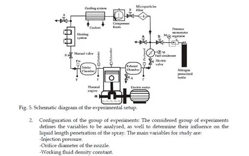
the importance of measuring the liquid phase penetration of the fuel in Diesel engines with direct injection, using sophisticated and complex measuring techniques.
Diesel spray characteristics
Depending on the mechanism to characterise, diesel spray can be analysed in a macroscopic or microscopic point of view. With the purpose of understanding in detail this process, the various physical parameters involved during the transition of a pulsed diesel spray will be expressed in this chapter, however it is essential to know the systems that make possible for an injection process to take place. These are the injection nozzle, active fluid to inject (liquid), and the working fluid on which the liquid is injected, as seen in figure 1.
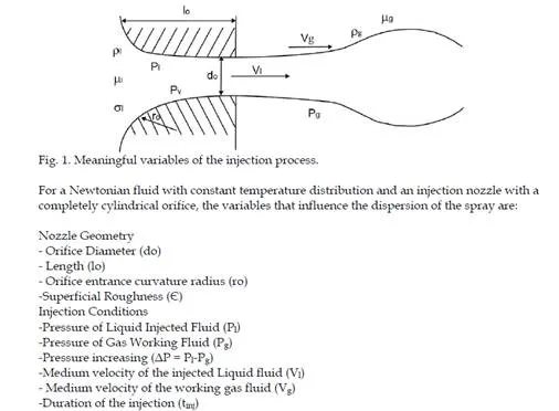
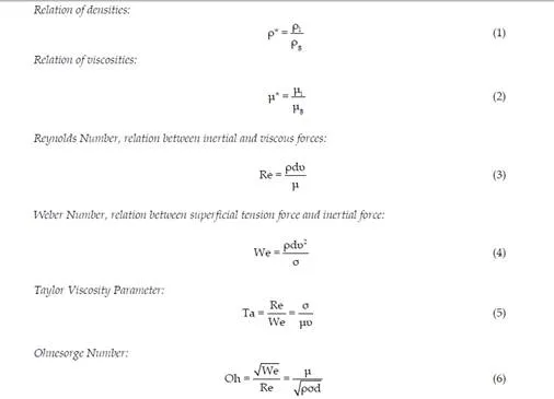
Reynolds Number: Density and kinematic viscosity must be particularised for liquid or gas, furthermore these properties can be evaluated for intermediate conditions between both fluid film conditions. These parameters can be divided into two groups:
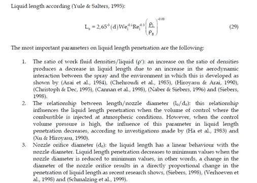
1. External flow parameters (relation of densities, Weber number, Taylor parameter), these parameters control the interaction between the liquid spray and the surrounding atmosphere.
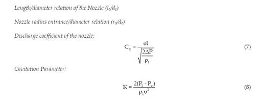
2. Internal flow parameters (Reynolds number, cavitation parameter, length/diameter relation, nozzle radius entrance/diameter relation, discharge coefficient): these parameters control the interaction between the liquid and the nozzle.
Macroscopic Characteristics
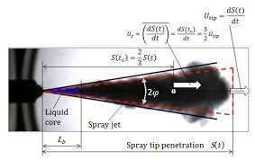
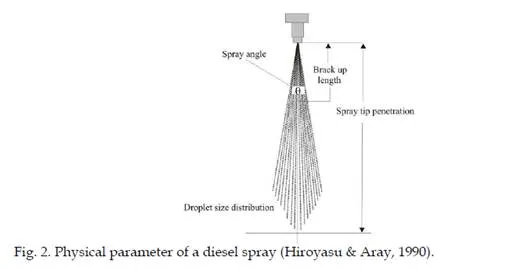
The macroscopic description of a diesel spray generally emphasise the interaction of the latter and the control volume where it is injected and mixed, and because of this the diesel spray can be defined with the following physical parameters (Figure 2.2):
1. Spray tip penetration
2. Spray angle
3. Breack up length
Front Penetration
The injection front penetration (S) is defined as the total distance covered by the spray in a control volume, and it’s determined by the equilibrium of two factors, first the momentum quantity with which the fluid is injected and second, the resistance that the idle fluid presents in the control volume, normally a gas. Due to friction effects, the liquids kinetic energy is transferred progressively to the working fluid. This energy will decrease continuously until the movement of the droplets depends solely on the movement of the working fluid inside the control volume. Previous studies have shown that a spray penetration overcomes that of a single droplet, due to the momentum that the droplets
Considering C1 and C2 experimental constants, deq to be the equivalent diameter, and C another experimental constant as a function of the discharge coefficient, it can be said that the discharge coefficient and the constant C have a direct dependence on the injector type used and in less measure on the working conditions. Therefore and according to (Hiroyasu
& Dent, 1990) proposal, the discharge coefficient (Cd) for a determined injector does not modify the constant C value. Other works of great importance concerning the penetration of spays in VCO nozzles were presented by (Bae & Kang, 2000), in which he classifies different types of sprays for different densities of the working fluid.
As a summary it can be said that the penetration of the spray basically depends on the following parameters:
-Injection pressure increasing ΔP: Increasing the injection pressure in relation to the control volume where the fuel is injected (ΔP), increases the velocity of the penetration of the spray
and hence the development of the latter will be easier at the beginning, (Hiroyasu et al.,
1980) and (Arai et al., 1984).
According to (Ahmadi et al., 1991), because a part of the liquid advances rapidly through the internal spray area where the aerodynamic interaction is poor, the injection pressure fluctuations are not related to the injections velocity. On the other hand, at the tip of the spray the high aerodynamic interaction causes the latter to lose velocity, making the recently injected liquid to reach and pass this slower moving tip, taking its place as the new spray tip and afterwards being slowed down as well by the control volumes surroundings. As well, (Nishida et al., 1992) and (Tinaut et al., 1993) suggest that the velocity of the droplets at the tip is usually slower than in other regions of the spray, so the simple fact that the velocity of the droplets is slower than the velocity of penetration demands a constant droplet renewal in the tip of the spray.
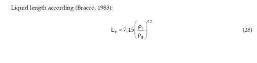
-Density ratio (ρ*): this dimensionless parameter ρ* or relation of densities, according to (Hiroyasu et al., 1980), (Arai et al., 1984) and (Payri et al., 1996), considerably affects the penetration of the spray, due to the fact that increasing the relation of densities causes the penetration to reduce considerably, this is because of the increase or reduction of the aerodynamic interaction, according to the respective parameter scale.
-Working fluid temperature (Tg): density reduction can be caused by the increase of the working fluids temperature, hence, the decrease of spray penetration. However, previous studies show that the spray’s temperature doesn’t produce significant effects in the penetration in relation to other parameters, (Hiroyasu et al., 1980) and (Arai et al., 1984).
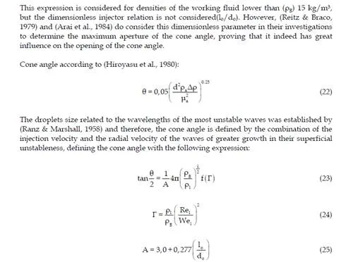
Cone angle
The cone angle is defined as the angle formed by two straight lines that stat from the exit orifice of the nozzle and tangent to the spray outline (sprays morphology) in a determined distance. The angle in a diesel spray is formed by two straight lines that are in contact with the spray’s outline and at a distance equivalent to 60 times de exit diameter of the nozzles orifice. This angle usually is between 5 and 30 degrees. This determines greatly the fuels macroscopic distribution in the combustion chamber. In one hand, the increase in angle decreases the penetration and can cause interference between sprays (when sprays are injected using multi-orifice nozzles) in the same chamber favouring the merging of droplets. On the other hand, an excessive penetration is favoured when the angle decreases lower than certain values, causing the spray to collide with the piston bowl or the combustion chamber.
In previous studies there have been a series of proposals to determine the cone angle, some of the most important are as follows:
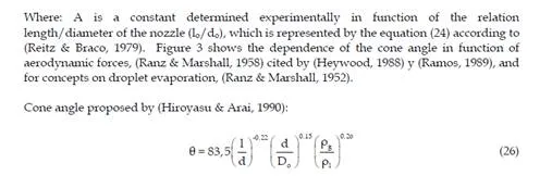
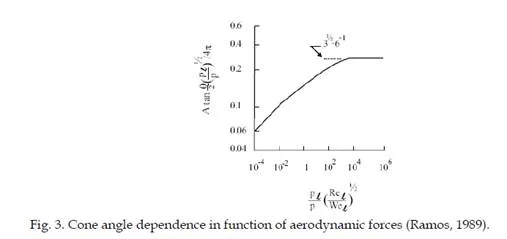
Where: Do represent the diameter of the nozzles jacket. With this expression it’s possible to determine the angle of opening of the fully developed spray, where the angle is practically a function of the nozzles orifice geometry and the dimensionless term of the relation of densities (ρ*). Others parameters such as cinematic viscosity can in some way modify the limits of the developed spray, but not the angle of the cone.
The cone angle is mainly affected by the geometric characteristics of the nozzle, the density ratio (ρ*), and the Reynolds number of the liquid, (Reitz & Bracco, 1979, 1982), apart from depending on other variable such as those described as follows:
-Increasing pressure (ΔP): An increase in the injection pressure causes an increase in the cone angle up to a maximum value, above decrease gradually.
-Density ratio (ρ*): An increase in the relation of densities is a factor that causes an increase in the cone angle due to an increase in the aerodynamic interaction, according to (Arrègle,
1998) and (Naber & Siebers, 1996), for values greater than (ρ* > 0.04) the cone angle tends to be independent of this parameter.
-Working fluid temperature (Tg): Increasing working fluid temperature, increases the evaporation process in the sprays exterior zone, consequently a decrease in the angle of the cone, (Hiroyasu et al., 1980).
Liquid Length
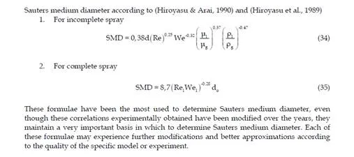
The liquid length of the spray is a very important characteristic to define the behaviour of the spray in the combustion chamber. This zone of the spray is also called continuous or stationary and it is understood as being from the nozzle exit to the point were the separation of the first droplets occur. To define this zone the use of diverse measurements methods and techniques is of vital importance. In the literature we find some of the most useful measurement methods and techniques in the analysis of the liquid length, (Hiroyasu & Arai,
1990), (Chehroudi et al., 1985), (Arai et al., 1984), (Nishida et al., 1992), (Gülder et al., 1992), (Christoph & Dec, 1995), (Zhang et al., 1997) and (Bermúdez et al., 2002, 2003).
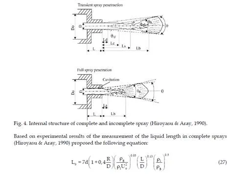
To analyze the internal structure of the spray, (Hiroyasu & Aray, 1990) identified two zones inside the atomizing regime, the zone of the incomplete spray and the zone of the complete spray. Figure 4 shows structure in a general way. The difference between them is due to the fact that with the incomplete sprays the disintegration of the surface of the spray begins at a certain distance from the point of the nozzle of the injector, indicating a distance Lc, while in the case of the incomplete sprays distance Lc is nearly cero and Lb is maintained virtually constant on increasing speed. Furthermore (Hiroyasu & Aray, 1990) show that cavitation greatly favours the atomization process in the complete spray regime.
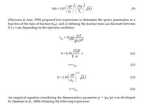
To define liquid length a series of expressions have been proposed which have been suggested in specific conditions according to each case and among the most relevant the following can be cited:
located in the front of the spray experiment, accelerating the surrounding working fluid, causing the next droplets that make it to the front of the spray an instant of time later to have less aerodynamic resistance. We must emphasise that diesel fuel sprays tend to be of the compact type, which causes them to have large penetrations.
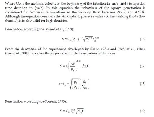
Several researchers have studied the front penetration and have found a series of correlations that allow us to establish the main variables that affect or favour the penetration of a pulsed diesel spray. The following are some of the most relevant:
From the theory of gaseous sprays, (Dent, 1971) was one of the pioneers in the study of spray phenomena. The author proposed an experimentally adjusted correlation which is applicable to pulsed diesel sprays; this correlation was the compared by (Hay & Jones, 1972) with other correlations, finding certain discrepancies between them. However, this correlation is considered to be applicable in a general form to diesel sprays
4. Working fluid temperature (Tg): working fluid temperature is one of the thermodynamic properties that strongly affect liquid length penetration, since the rate of combustible vaporization is directly related to the energy content of the working fluid in the inside of the cylinder (e.g., high temperatures) and in the degree of the mixture of both fluids (injected fuel-gas or air) (Christoph & Dec,
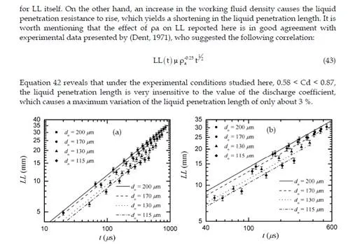
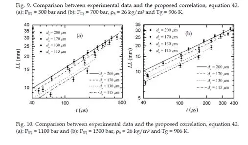
1995). However, working fluid temperature has no relevant effect at high pressure injection because both, an increase in the speed of injection and the amount of fuel injected, ease the effect with respect of low pressures, (Zhang et al., 1997). An increase in working fluid temperature at constant density causes and increase in the specific energy of the latter and therefore a decrease in liquid length during spray penetration is a consequence of high drag of vaporization energy towards the fuel, (Siebers, 1999).
5. Fuel temperature (Tf ): fuel temperature is a variable that greatly affects liquid length penetration in such a way that on increasing the temperature of the latter liquid length tends to decrease lineally. It has been proven that at under conditions of low temperature and working fuel density there are more significant effects that under high conditions of temperature and density, because in the latter case the effect witch respect an absolute scale is insignificant, (Siebers, 1998).
6. Physical-Chemical properties of the fuel: these properties of the fuel (i.e., density, viscosity and volatility) have a considerable impact on liquid length penetration
with volatility being the most influential property on penetration. (Siebers, 1998,
1999) observes that a low volatility fuel requires more energy to be heated and then evaporate than a high volatile fuel. Therefore, for a low volatile fuel, liquid length penetrates much more than a more volatile fuel because the amount of energy dragged towards the fuel depend basically on the process of evaporation.
Liquid length of a diesel spray is a parameter of much interest in the study of the injection- combustion process. In later topics in this same chapter we will discuss this parameter where a complete experimental analysis of the characterization of the liquid length of a diesel spray is approached.
Microscopic Characteristics
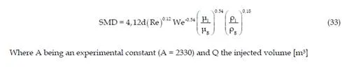
The macroscopic description is characterized by the content of droplets of diverse sizes and the changes on the changes in their special kinetics. For example, the atomization mechanism is responsible for distributing the droplets in the injection process and to a great extent the good distribution of the droplets in relation to their size depend on it. Generally the quality of the atomization of a liquid spray can be estimated on the medium diameter of the droplets. A determined medium diameter represents the equivalent diameter that characterizes the entire group of the droplets of the spray. Equation (30) establishes the general form based on which all the correlations that determine Sauters medium diameter have been defined.
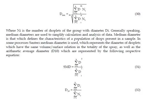
It must take into account that using medium diameters is very useful to simplify droplet populations existing in an atomizing process. For this reason it is essential to use the distribution of droplet size.
Droplet size distribution
The diameter of the droplets obtained as a result of atomization is based on a series of parameters as follows:
1. Rate of injection: the diameter of the droplet increases with the rate of injection as
an increase in the volume of the injected liquid produces a greater drag of the working fluid, the aerodynamic interaction grows and the critical size of the droplets increases. Apart from this, increasing the numeric population of droplets intensifies de coalescence, resulting in a growth in the geometry of the droplets.
2. Density ratio (ρ*): the relation of densities has two opposing effects on the size of the droplets, intensification of atomization and the possibility that there will be coalescence. On increasing the relationship of densities a greater aerodynamic interaction exists, which causes the droplets to slow down and an increase in the numerical population in their field.
3. Working fluid temperature (Tg): on increasing working fuel temperature their is an increase on the rate of evaporation, due to which at the beginning of this the droplets with small diameters tend to evaporate completely while those droplets with greater diameters maintain a stable geometry until they evaporate completely.
4. Spatial evolution of the size of the drops: the average size of the droplets tends to grow in relation to the increase of the distance between the drops and the injector point. In some studies it has been suggested that the average diameter of the drops is greater in the direction of the radius of the spray while other suggest the opposite, that is the medium diameter is reduce in relation to the distance from it.
5. Evolution of the diameter of droplets during time: It’s generally considered that the medium diameter of the droplets decreases at the point of the spray and increases at the tail, while in areas distant from the injector they maintain a rate of constant values. Generally speaking, the sizes of the droplets tend to diminish at the beginning of the injection and grow at the end.
The most common formulas to determine Sauters medium diameter are: Sauters medium diameter according to (Hiroyasu & Kadota, 1974
Measurement techniques
Some problems of fluid mechanics are complex where multiphase systems are concern and when combustion phenomena are produced. In many cases current knowledge is still incomplete due to the complexity of the physical-chemical processes: (non-stationary processes, irreversible processes and out-of-balance chemical reactions) that occur at the limits of different scientific disciplines such as fluid mechanics, thermodynamics and chemistry. In order to progress in its study we need available experimental data that provide information of the different processes and degrees of interest for the study, such as for example, mass and energy transport, movement and the size of particles, concentration of the different species, thermodynamic properties, and chemical composition among others.
The physical phenomena of interaction matter-radiation (absorption, dispersion, interference, diffraction, among others) are very sensitive to small variations in the localize physical parameters of the fluid, and furthermore they do not interact with the physical processes in the environment of fluid mechanics, and so are useful in the analysis of these problems. Technological advance in diverse fields basically optics, electronics and information technology have allowed for this development of equipment able to measure some localized physical parameters of fluids in a very precise way, and are the basis for the development of optical techniques of measurement and visualization used in studies of fluid mechanics.
Classical visualization techniques
The classical visualization methods are based on the variations of the refraction rate that are produced in the fluids heart due to the changes in its physical properties. When an beam of light propagates through a fluid, the variations of the refraction rate causes variations in both the intensity and in wave phase, therefore the emerging light contains information of the fluid properties in the light beam trajectory propagation. Basically these optical techniques can be divided in 3 types: Shadowgraphy, Schlieren and Interferometry, which
have been used since the 1860’s, (Foucault, 1859) in France and (Toepler, 1864) in Germany gave the first insights of the Schlieren technique. Toepler was the first to develop this technique for the study of liquids and gas flow, and later on used by (Hayashi et al., 1984) and (Konig & Sheppard, 1990), among others.
-Shadowgraphy: the environment is illuminated with a straightening of a light beam and the image is taken after the emerging light propagates freely through the space. The visualization technique with diffused rear illumination is a similar technique but the environment is lit up with a diffuse beam light. The difference between these techniques consists on placing a diffuser between the beam and the environment to illuminate. These techniques allow visualizing the liquid phase of the fuel spray and are greatly used in the study of the injection process of combustion internal engines. The visualization with rear diffused illumination technique allows the estimation of the different macroscopic parameters in an injection process. (Zaho & Ladommatos, 2001) have studied the spray penetration and consider this technique to be reliable and easy to use for this type of analysis.
-Schlieren photography: this technique is similar to that of the shadowgraphy, the difference is that the image is taken after a spatial filtering in the image plane of the light source. Adjusting adequately the spatial filtering dimensions it is possible to visualize both the liquid and vapour phase of the fuel spray, but not to quantify them. These techniques have been used in the injection and combustion processes of the internal combustion engine (Preussner et al., 1998), (Spicher & Kollmeire, 1986) and (Spicher et al., 1991), as well as in the analysis of propulsion systems (Murakamis & Papamoschou, 2001) and (Papampschou,
2000).
Scattering techniques
The classical visualization techniques incorporate the information throughout the beams propagation trajectory, by which the information about the existing three-dimensional structures in the vessel of the fluid is lost. This information can be obtained illuminating the fluid with planes of light and taking pictures of the dispersed light by the environment, normally in the perpendicular direction of the plane. This kind of visualization techniques can be included in a much general group which is the scattering technique. The light scattering phenomena can be of two types, elastic or inelastic, depending on if the process produces or not the radiation frequency.
Elastic scattering techniques
The elastic dispersion phenomena of light are studied within the theory of Lorenz-Mie. There are basically two approximations depending on the size of the particles: Mie scattering and Rayleigh scattering.
-The Mie scattering is an interaction of the elastic type of light with particles of much greater size than that of its wave length (droplets, ligaments, among others). The characteristics of the scattered light are related to the form, size, refraction rate and number of scattering particles. These properties are the basis of the different optical techniques of measurement described as follows:
1. Visualization with a laser sheet the fluid is illuminated with a laser sheet beam obtaining images of the scattered light (Mie regime), normally on the perpendicular direction of the sheet. This technique allows estimating the macroscopic characteristics of fuel sprays and analysing the existence of internal structures, ligaments, among others. This technique is one of the most used in the study of the injection process in an internal combustion engine (Dec, 1992) and (Preussner et al., 1998).
2. Technique of laser anemometry: it is based on the interaction of coherent light with the existing particles in movement inside the heart of the fluid in such a way that the sizes of these particles allow them to be treated in Mie scattered imaging. These interactions produce a change in the frequency of radiation (Doppler Effect) that can be related to both the speed and size of the particles. In the so called Laser Doppler Anemometry (LDA), two coherent light beams interact in one region (control volume) with the existing moving particles in the fluid and the fluctuation of the disseminated light intensity allows the estimation of the particles speed. (The obtained light intensity is basically intensity with a background modulated by a cosine function, whose temporal variation depends solely on the frequencies of the dispersed beams. The frequency of modulation for this signal can be related to the velocity of the particles). The Phase Doppler Anemometry (PDA) is based on the same principle but it uses several photo sensors placed in different spatial positions. With which it’s possible to estimate the diameter of the diffusive particles considering them spherical by the temporal phase lag between signals received by each photo detector. This technique requires a series of optical accessories that difficult its use in measurement of a real thermo engine. Although some investigators (Auriemma et al., 2001), (Corcione et al., 1998), (Cossali et al., 1996), (Georjon et al., 1997) and (Guerrassi & Champoussin, 1996) have used the phase Doppler anemometry to develop very specific analysis, the mayor usage is still the characterization of the distribution of diameters and velocities of fuel droplets in accessible optical models that simulate similar conditions of those found in real thermal engines (Arrègle, 1998) and (Jiménez et al., 2000).
3. The velocimetry imaging techniques allow velocity field measuring in a fluids plane that is illuminated with a screen of light. There are several ways to use these techniques, depending on the method selected to register and to process information, however all of them are very important: in Particle Image Velocimetry (PIV) the fluid is illuminated with several light pulses and the instant images are registered using multiple exposure techniques. The instant velocities are obtained dividing the particles displacement in each time consecutive image by two pulses. In Particle Shadow Velocimetry the fluid is illuminated in a long period of time in which the displacement of the particles are registered as lines on the image and the velocities are calculated dividing the line length by time interval. In Particle Tracking Velocimetry a series of consecutive exposures take place (several light pulses) in one image and the velocity is estimated by tracking the particles. The velocimetry techniques are used mainly to analyse flow of gases en the thermal engine. Some of the most recent applications for this technique can be found in the literature (Choi & Guezennec, 1999), (Kakuhou et al., 1999), (Nauwerck et al., 2000), (Neussert et al., 1995), and (Trigui et al., 1994), where the main application is focussed to the study of mixture formation inside the combustion chamber of a thermal engine, furthermore it considered to be one of the best techniques for this kind of analysis.
4. Rayleigh scattering is of the elastic kind, where the size of particles is much smaller of that of the lights wavelength, for example the gas molecules. The intensity of the scattered light is proportional to the total density of all kinds of existing particles inside the illuminated zone and provides images of global concentration of all the species, although it doesn’t allow discrimination between them. Furthermore for example, the Rayleigh signal for a particle approximate 1 µm is close to twenty orders of magnitude lower than the Mie signal, for which the signal is highly affected by both the presence of large particles and by the background light. The two most commonly used procedures to reduce the interference of particles are shown by (Zhao et al., 1993). The main researchers using the Rayleigh technique (Espey & Dec, 1994), (Lee & Foster, 1995) and (Zhao et al., 1991) have been basically to determine concentrations of vapour and liquid phases and mainly in zones with high flame presence. As well as in the temperature measure and species concentration for the combustion diagnostic.
Inelastic scattering techniques
On the other hand, the inelastic scattering of light is studied in the quantum mechanics field, specifically in the study of matter-radiation interaction phenomena. These phenomena are extremely sensitive to the frequency of radiation and the species chemical composition because they depend on electronic transitions between molecular energy levels caused by the absorption of photons of defined frequency that stimulate the molecules to higher energetic conditions. After which the molecules come to stable conditions releasing radiant energy where its spectral characteristics are also very well defined. Different optical techniques of measure are bases on these phenomena, detailed as follows:
-Laser Induced Incandescence is a technique based on the thermal emission that is produced when the carbon particles are stimulated with a very intense electromagnetic radiation. The obtained signal is proportional to the volume fraction of the carbon particles concentrated in the measured zone. Because of this, the technique is very useful for the study of combustion processes (Dec, 1992), (Dec et al., 1991), (Dec & Espey, 1992), (Winklhoefer et al., 1993) and (Zhao & Ladommatos, 1998), mainly to determine the qualitative distribution of soot in the high radiation zone during a injection-combustion process.
-Laser Induced Fluorescence (LIF) is a technique based on the fluorescent properties that some molecules present. When these molecules absorb electromagnetic energy of a determine frequency they acquire a higher energetic condition (stimulation) and afterwards they return to their original energetic state releasing this energy (fluorescence). The spectral characteristics of this radiation are determined by the molecules characteristics. If the fluid doesn’t have fluorescent molecules, molecular tracers that present fluorescence can be added. For example: NO, NO2, acetone, biacetyl, rodamina, or different colorants. The fluorescent signal is proportional to the density of the tracers inside the illuminated zone. In many cases the environment is illuminated using laser beam sheet and the technique is then known as planar induced laser fluorescence (PLIF). In the planar laser induced exciplex fluorescence (PLIEF) tracers called exciplex (complex excitation), like for example: naphthalene mixtures and TMPD (tetramethyl-1,4-phenylenediamine) that allow to separate spectrally the corresponding liquid and vapour phase fluorescence of a biphasic system, and therefore measure simultaneously each ones concentration (Juliá, 2003). Although this
technique has much application in injection-combustion processes (Felton et al., 1995), (Fujimoto et al., 1997), (Hiroshi et al., (1997), (Kido et al, 1993) and (Kim & Ghandhi, 2001), it is not considered to be the most appropriate to detect species when compared to other, like for example: Mie-Scaterring. This is due to the incoherencies presented when detecting species in these types of processes (Preussner et al., 1998) and (Takagi et al., 1998). Phosphorescent particle tracking (PPT) is a similar technique to that of particle tracking velocimetry (PTV). The phosphorescence is an inelastic diffusion of light characterized by it long temporal duration, much higher than that of fluorescence, which makes it ideal to track the movement of particles in the fluid.
Experimental characterization of the liquid length penetration
Introduction
The main objective of this section is to carry out the characterization of the liquid length penetration of a diesel spray. To achieve this it has been necessary to consider a group of experiments which allow the determination of the influence that the injection parameters and the thermodynamic variables have upon the penetration of a diesel spray in evaporative conditions. The first developed study is based on the analysis of the penetration of the spray in its liquid phase, where it is expected to define the degree of influence that the following have over this phenomena: thermodynamic variables (pressure, temperature and density) present in the combustion chamber at the moment when the fuel is injected, the injection pressure and the geometry of the nozzle. To make this study it’s necessary to use the ombroscopy technique for the taking of digital images, as well as an acquisition system to process data. It is to point out that the ombroscopy has been the most used technique in the macroscopic characterization of diesel sprays, specifically in the study of the liquid phase penetration. As mentioned in section 4, the techniques of measure to carry out studies of the liquid phase of diesel sprays are very diverse. The most used until know are expressed in this chapters literature. (Cambell et al., 1995), (Canaan et al., 1998), (Christoph & Dec, 1995), (Felton et al., 1995), (Hiroyasu & Miao, 2002) and (Knapp et al., 1999).
Experimental work approach
A working plan that groups the different experiments to carry out has been structured in such a way to analyse qualitatively the injection process. To achieve this, the experimental work has been planned as follows:
The use of the experimental in system with the inert atmosphere method and through the ombroscopy technique analyse the penetration of the liquid phase of the diesel spray.
– Parametric analysis to consider:
1. Influence of the injection process on the liquid length penetration.
2. Influence of the diameter of the nozzle on the liquid length penetration.
The analysis of the liquid length penetration is useful to determine the geometric design of combustion chambers for high speed regime diesel engines with direct injection. For example, in low speed regime and light load the hydrocarbon emissions will be reduced if the contact of the spray (liquid length) with the combustion chambers wall is avoided. For high speed regimes and heavy loads, the reduction of fumes can be achieved by contact
between the spray and the chamber wall. Because of these, the necessity to measure the liquid penetration in diesel engines of direct injection emerges, motivating the use of measure techniques even more complex and sophisticated.
In previous studies (Christoph & Dec, 1995) investigated the effects that temperature and the fluids density have on the liquid phase penetration. In this study they used a Diesel engine witch optical access views, and through the elastic-scatter technique they obtained images of the spray. (Zhang et al., 1997) analyzed the effects that the injection pressures, diameter of the nozzle and admission air temperature have on liquid length penetration. For this they used a compression machine which had an equivalent compression ratio to that found in a Diesel engine. In this analysis an argon laser beam was used as the light source and an E-10 camera was also used to capture the images. (Siebers, 1998) investigated the maximum axial penetration of the liquid phase of an evaporated diesel spray in a chamber of constant volume, using the Mie-scattered technique for image capturing. The main altered parameters where the injection pressure, orifice diameter of the nozzle, temperature and density of the working fluid in the inside of the chamber.
The investigation of the sprays liquid phase for a common rail system at high temperatures was made by (Bruneaux & Lemenand, 2002). The variation in parameters in this investigation where: the injection pressure, the temperature of the working fluid and the diameter of the nozzle. This study was made in a chamber similar to the one used by (Verhoeven et al., 1998), in which it was possible to maintain high pressures and temperatures inside the chamber and so simulating similar conditions found in a real Diesel engine. The technique of measure used was based on a light source supported by a planar laser induced exciplex fluorescence system and a charged-coupled device (CCD) camera to capture images. It’s evident that each investigator uses in his experiments defined and heterogeneous techniques of measure. However occasionally and in some complexity degree the final results tend to be very similar independently of the used, reason why the motivation to develop the basis for the experiments presented in this chapter arose with one of the most flexible visualization techniques, the ombroscopy.
The characterization of the liquid length penetration of an evaporated diesel spray was done under the following methodology:
1. Experimental system configuration: to undertake the experiments that lead to obtain information about the liquid length penetration of the spray without flame, it has been necessary to form the experimental system in an inert atmosphere. Furthermore to conceive as a first phase the use of ombroscopy technique to obtain images of the liquid phase of the spray (Figure 5 shows the schematics diagram of the global experimental setup configuration).
Mathematical correlation
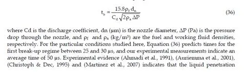
Liquid phase penetration of a jet injected into an inert environment has well defined stages. The first stage begins with the injection and ends when the jet breaks up. This is the intact length stage or the first break-up regime, (Hiroyasu & Aray, 1990) suggested the following correlation to estimate the time for the first break-up regime to occur:
Determination of the fuel injection onset
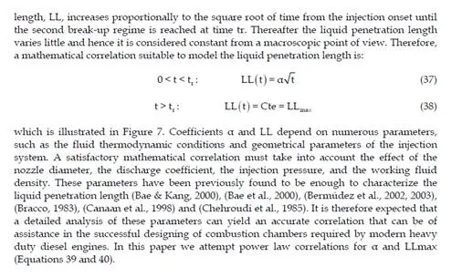
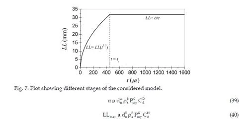
The fuel injection onset can be determined assuming that LL increases proportionally to the square root of time until the second break-up regime is reached at tr, i.e. LL = α t1/2 for
0 < t < tr. Time tr is defined as the time when the ratio between LL to t1/2 with a correlation
coefficient R2 = 99 %. Coefficient α is estimated by fitting experimental data measured before the second break-up regime is reached, as shown in Figure 8, where the experimental data can be approximated by LL = 1.07 t0.497 with a correlation coefficient R2 = 99.8 %.
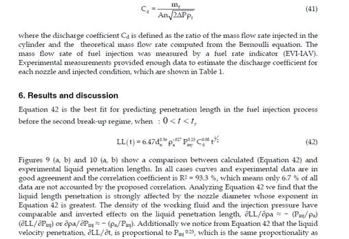
Conclusions and remarks
Experimental measurements were carried out to estimate the liquid penetration length of a diesel fuel jet injected in an inert environment. The effects of the characteristic parameters, i.e. the nozzle diameter, discharge coefficient, injection pressure, and working fluid density were analyzed. The transient fuel injection process was recorded using optical access, and the liquid penetration length before the second break-up regime was measured using the ombroscopy technique. The aim of the present research is to generate a correlation that accurately predicts liquid penetration length at conditions typical of modern Heavy Duty common rail diesel engines operating with direct fuel injection. A statistical analysis of our experimental measurements suggests a power function correlation to model the liquid penetration length. The proposed model is in good agreement with experimental data and yields a correlation coefficient R2 = 93.3 %. Furthermore, the suggested correlation illustrates important details about how the main parameters affect the fuel injection process. The nozzle diameter has the greatest effect on liquid penetration length. A reduction in nozzle diameter yields a shorter penetration length because it causes an earlier start of the second break-up regime. Increasing the injection pressure provokes premature droplet break-up within the jet, which results mainly due to cavitation at the nozzle exit. If the working fluid density in the combustion chamber increases the penetration length is shorter and the second break-up regime is delayed due to the free-share flow between the working fluid and the fuel jet, which produces higher evaporation rates of droplets from the diesel jet. Finally, under the experimental conditions studied here, the discharge coefficient has a negligible effect on the liquid penetration length. However, the discharge coefficient influences the cavitation phenomenon at the nozzle exit and modifies the droplet velocity within the jet.