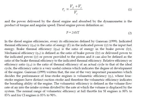
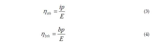
The four-stroke direct-injection diesel engine typical was measured and modeled by Bakar et al (2007) using GT-POWER computational model and has explored of diesel engine performance effect based on engine speeds. GT-POWER is the leading engine simulation tool used by engine and vehicle makers and suppliers and is suitable for analysis of a wide range of engine issues. The details of the diesel engine design vary significantly over the engine performance and size range. In particular, different combustion chamber geometries and fuel injection characteristics are required to deal effectively with major diesel engine design problem achieving sufficiently rapid fuel-air mixing rates to complete the fuel- burning process in the time available. According to Heywood (1988) and Ganesan (1999), a wide variety of inlet port geometries, cylinder head and piston shapes, and fuel-injection patterns are used to accomplish this over the diesel size range. The engine ratings usually indicate the highest power at which manufacturer expect their products to give satisfactory of power, economy, reliability and durability under service conditions. Maximum torque and the speed at which it is achieved, is usually given also by Heywood (1988). The importance of the diesel engine performance parameters are geometrical properties, the term of efficiency and other related engine performance parameters. The engine efficiencies are indicated thermal efficiency, brake thermal efficiency, mechanical efficiency, volumetric efficiency and relative efficiency (Ganesan, 1999). The other related engine performance parameters are mean effective pressure, mean piston speed, specific power output, specific fuel consumption, intake valve mach index, fuel-air or air-fuel ratio and calorific value of the fuel (Heywood, 1988; Ganesan, 1999; Semin et al., 2007). According to Heywood (1988) in the diesel engine geometries design written that diesel engine compression ratio is maximum cylinder volume or the displaced volume or swept and clearance volume divided by minimum cylinder volume. And the power delivered by the diesel engine and absorbed by the dynamometer is the product of torque and angular speed. The engine efficiencies, every its efficiencies defined by Ganesan (1999).
Important
In this chapter has investigated the effect of injector nozzle holes diameter geometries on the performance of diesel engine such as indicated power, indicated torque, fuel consumption and fuel in-engine cylinder. The investigation is using computational modelling based on variation engine speeds.
Engine Performance Review
In the diesel engine geometries design by Heywood (1988), the diesel engine compression ratio is maximum cylinder volume or the displaced volume or swept (Vd ) and clearance volume (Vc) divided by minimum cylinder volume (Vc). The diesel engine compression ratio can be calculated as below:
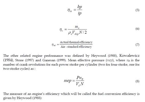
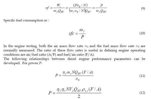
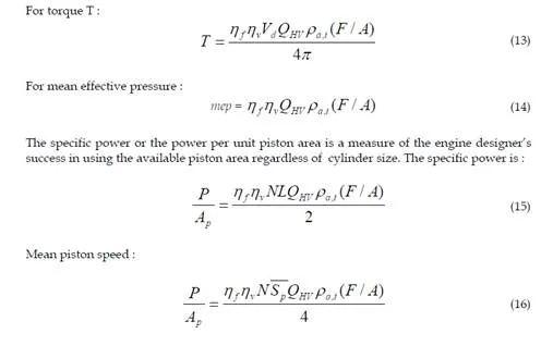
Heywood (1988) written that, specific power is thus proportional to the product of mean effective pressure and mean piston speed. These relationship illustrated the direct importance to engine performance of high fuel conversion efficiency, high volumetric efficiency, increasing the output of a given displacement engine by increasing the inlet air density, maximum fuel/air ratio that can be useful burned in the engine and high mean piston speed.
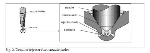
Modelling of Injector Nozzle Holes
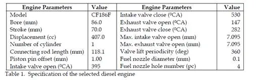
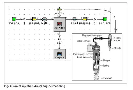
The four-stroke direct-injection (DI) diesel engine was presented in this chapter. The specification of the selected diesel engine was presented in Table 1. To develop the four- stroke direct-injection diesel engine modeling is step by step, the first step is open all of the selected diesel engine components to measure the engine components part size. Then, the engine components size data will be input to the software library of the all engine components data. To create the model, select window and then tile with template library from the menu. This will place the template library on the left hand side of the screen. The template library contains all of the available templates that can be used in computational modeling. Some of these templates those that will be needed in the project need to be copied into the project before they can be used to create objects and parts. For the purpose of this model, click on the icons listed and drag them from the template library into the project library. Some of these are templates and some are objects that have already been defined and included in the template library (Gamma Technologies, 2004). This chapter focused on fuel nozzle hole of fuel injector. The engine modeling is according to Semin et al. (2007) as shown in Fig. 1.
Whenever the computational simulation is running, the computational model produces several output files that contain simulation results in various formats. Most of the output is available in the post-processing application. The software is powerful tool that can be used to view animation and order analysis output (Gamma Technologies, 2004). After the simulation was finished, report tables that summarize the simulations can be produced. These reports contain important information about the simulation and simulation result in a tabular form. The computational simulation of the engine model result is informed the engine performance. The running simulation result in this research is focused on the engine performance data based on variation of fuel nozzle material hole diameter size, diameter number and the different engine speed (rpm). The diesel engine model was running on any different engine speeds in rpm, there are 500, 1000, 1500, 2000, 2500, 3000 and 3500. The variations of injector fuel nozzle holes number are based on multi holes and multi diameter holes, the simulation model there are started from the injector fuel nozzle 1 hole, 2 holes, 3 holes, 4 holes, 5 holes, 6 holes, 7 holes, 8 holes, 9 holes and 10 holes.
Effect of Injector Nozzle Holes on Fuel in Engine Cylinder
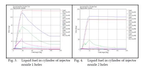
The simulation results are shown in every cases, such as case 1 is on 500 rpm, case 2 is on
1000 rpm, case 3 is on 1500 rpm, case 4 is on 2000 rpm, case 5 is on 2500 rpm, case 6 is on
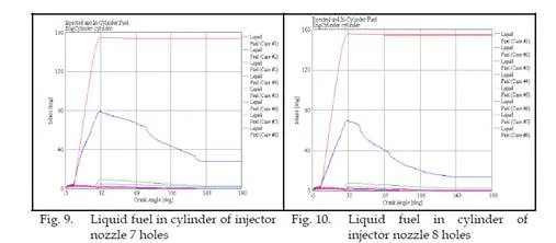
3000 rpm, case 7 is on 3500 rpm and case 8 on 4000 rpm. Numerous studies have suggested that decreasing the injector nozzle orifice diameter is an effective method on increasing fuel air mixing during injection (Baik, 2001). Smaller nozzle holes have found to be the most efficient at fuel/air mixing primarily because the fuel rich core of the jet is smaller. In addition, decreasing the nozzle hole orifice diameter, would reduce the length of the potential core region. Unfortunately, decreasing nozzle holes size causes a reduction in the turbulent energy generated by the jet.
Since fuel air mixing is controlled by turbulence generated at the jet boundary layer, this will offset the benefits of the reduced jet core size. Furthermore, jets emerging from smaller nozzle orifices were shown not to penetrate as far as those emerging from larger orifices. This decrease in penetration means that the fuel will not be exposed to all of the available air in the chamber. The effect of fuel nozzle holes number and geometries of in-cylinder engine liquid fuel are shown in Fig. 3 – Fig. 12,
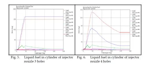
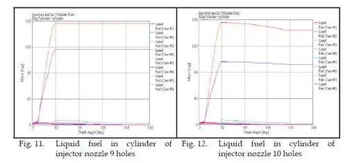
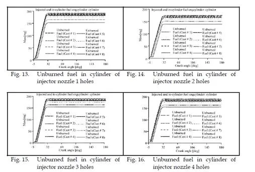
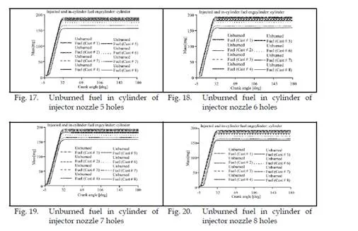
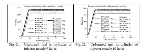
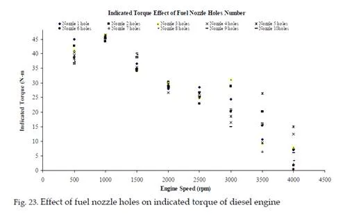
For excessively small nozzle size, the improvements in mixing related to decreased plume size may be negated by a reduction in radial penetration (Baumgarter, 2006). This behavior is undesirable because it restricts penetration to the chamber extremities where a large portion of the air mass resides. Furthermore, it hampers air entrainment from the head side of the plume because the exposed surface area of the plume is reduced. It has been suggested that a nozzle containing many small holes would provide better mixing than a nozzle consisting of a single large hole. The effect of injector nozzle multi holes in-cylinder engine unburned fuel are shown in Fig. 13 – Fig. 22.
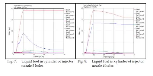
The optimal nozzle design would be one that provided the maximum number of liquid fuel burn in combustion process and minimum number of liquid fuel unburned. Theoretically, a
10 holes nozzle satisfies this requirement. Unfortunately, jets emerging from a 10 holes
nozzle tended to be very susceptible. All of the nozzles examined and the result shown that the seven holes nozzle provided the best results for any different engine speeds in simulation and the best performance shown on low speed engine.
Effect of Injector Nozzle Holes on Engine Performance
The simulation result on engine performance effect of injector fuel nozzle holes number and geometries in indicated power, indicated torque and indicated specific fuel consumption (ISFC) of engine are shown in Figure 23 – 25. The injector fuel nozzle holes orifice diameter and injector nozzle holes numbers effect on indicated power, indicated torque and ISFC performance of direct-injection diesel engine was shown from the simulation model running output. An aerodynamic interaction and turbulence seem to have competing effects on spray breakup as the fuel nozzle holes orifice diameter decreases. The fuel drop size decreases if the fuel nozzle holes orifice diameter is decreases with a decreasing quantitative effect for a given set of jet conditions.
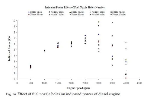
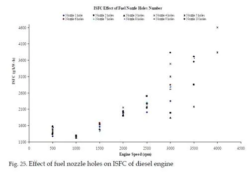
Fuel-air mixing increases as the fuel nozzle holes orifice diameter fuel nozzle holes decreases. Also soot incandescence is observed to decrease as the amount of fuel-air premixing upstream of the lift-off length increases. This can be a significant advantage for small orifice nozzles hole. However, multiple holes orifices diameter required to meet the desired mass flow rate as orifice diameter decreases. In this case, the orifices diameter need to placed with appropriate spacing and directions in order to avoid interference among adjacent sprays. The empirical correlations generally predict smaller drop size, slower penetrating speed and smaller spray cone angles as the orifice diameter decreases, however the predicted values were different for different relation. All of the nozzles have examined and the results are shown that the five holes nozzle provided the best results for indicted torque, indicated power and ISFC in any different engine speed in simulation.
Conclusion
All of the injector nozzle holes have examined and the results are shown that the seven holes nozzle have provided the best burning result for the fuel in-cylinder burned in any different engine speeds and the best burning is in low speed engine. In engine performance effect, all of the nozzles have examined and the five holes nozzle provided the best result in indicted power, indicated torque and ISFC in any different engine speeds.

Comments are closed