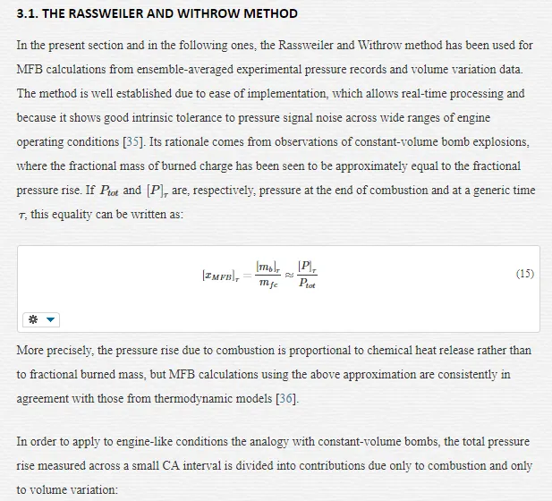
In the context of a Spark Ignition engine, the inherent complexity of premixed combustion is exacerbated by a range of engine variables that render the process highly transient in nature and not fully predictable. The present work aims to contribute to the continuous research effort to better understand the details of combustion and be able to model the process in gasoline SI engines. Coexisting fossil fuels depletion and environmental concerns, along with an alarming connection between traditional internal combustion engines emissions and human health degradation [1], have in recent years driven a strong research interest upon premixed SI combustion of energy sources alternative to gasoline, including liquid alcohols like ethanol, and gaseous fuels like hydrogen. However, the advancements enjoyed by gasoline-related technology and infrastructure in the last 40 years have eroded the potential advantages in efficiency and emissions offered by alternative fuels [2], and the SI engine running on gasoline continues to be the most common type of power unit used in passenger cars (Port-Fuel Injection gasoline engines accounted for the vast majority (91%) of all light-duty vehicle engines produced for the USA market in 2010 [3]).
The characteristics which make the gasoline engine well suited to light-weight applications include relatively high power to weight ratio, acceptable performance over a wide range of engine speeds, the vast infrastructure for gasoline and lower manufacturing costs when compared to diesel or more modern hybrid technologies [4]. The continuing exploitation of spark ignition engines reflects a history of successful development and innovation. These have included the electronic fuel injection system, exhaust emissions after-treatment, Exhaust Gas Recirculation and, increasingly, the use of some form of variable actuation valve train system. The modern SI engine, addressed to as high-degree-of-freedom engine by Prucka et al. [5], may also feature flexible fuel technology, typically to allow running on ethanol-gasoline blended fuels.
As the technology advances, the number of engine actuators increases and so does the number of variables that may potentially modify the combustion process. Methods of combustion control based on look-up tables may well be implemented in high-degree-of-freedom engines, for example to set optimal spark timing and phase combustion appropriately across Top Dead Centre, but are not well-suited during transient operation, when the boundary conditions are changing on a cycle-to-cycle basis. Whilst controlling the combustion process in highly complex engine architectures becomes more challenging, the development of straightforward modelling approaches, which allow reliable inclusion within real-time feed-forward engine controllers become essential to ensure improved performance and fuel efficiency also during transient or variable operation.
The premixed, homogeneous charge gasoline combustion process in SI engines is influenced by the thermo-chemical state of the cylinder charge. Significant factors are local temperature and pressure, stoichiometry and the contents of burned gas within the combustible mixture; these quantities affect rate of burning and consequent in-cylinder pressure development. The combustion process is also greatly influenced by cylinder bulk motion and micro-scale turbulence. Understanding the connection between charge burn characteristics and relevant engines operating variables in the context of modern technologies is extremely useful to enable and support engine design innovation and the diagnosis of performance. The present chapter explores the evolution of the combustion process in modern-design gasoline engines, as indicated by the cylinder charge Mass Fraction Burned variation and combustion duration, and the most relevant factors influencing these. It also explores the use, accuracy and limitations of recently-proposed empirical, non-dimensional (or simplified thermodynamic) combustion models which respond to the requirements of fast execution within model-based control algorithms, and discusses relevant results, which entail the use of Variable Valve Timing systems. An exemplar simplified quasi-dimensional models is also presented at the end of the chapter, along with some relevant results concerning an application to flexible fuel, gasoline/ethanol operation. All the experimental data and models discussed here refer and are applicable to stable combustion, typically identified by a Coefficient of Variability of the Indicated Mean Effective Pressure (CoV of IMEP) smaller or equal to 6% [6]. Although the importance of cycle-by-cycle variability is acknowledged, as this may arise from highly diluted combustion, the topic of unstable combustion has not been the focus of the present work.
Premixed combustion in SI engines
The present section reviews important features of the premixed combustion process in SI engines, introducing basic terms and definitions of relevant variables and combustion indicators. Ample space is dedicated to the working principles of VVT systems and how these may fundamentally affect the combustion process. This section ultimately provides definitions and methods of determination of in-cylinder charge diluent fraction, as the one most influential variable on combustion strength, duration and stability, in the case of engines fitted with a VVT system.
OVERVIEW OF FLAME PROPAGATION MECHANISM
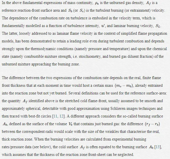
Detailed observations of development and structure of the flame in SI engines can be made by using direct photographs or other methods such as Schlieren and shadowgraph photography techniques [6, 7]. The initial stage of the combustion process is the development of a flame kernel, centred close to the spark-plug electrodes, that grows from the spark discharge with quasi-spherical, low-irregular surface; its outer boundary corresponds to a thin sheet-like developing reaction front that separates burned and unburned gases. Engine combustion takes place in a turbulent environment produced by shear flows set up during the induction stroke and then modified during compression. Initially, the flame kernel is too small to incorporate most of the turbulence length scales available and, therefore, it is virtually not aware of the velocity fluctuations [8]. Only the smallest scales of turbulence may influence the growing kernel, whereas bigger scales are presumed to only convect the flame-ball bodily; the initial burning characteristics are similar to those found in a quiescent environment (a laminar-like combustion development). As the kernel expands, it progressively experiences larger turbulent structures and the reaction front becomes increasingly wrinkled. During the main combustion stage, the thin reaction sheet becomes highly wrinkled and convoluted and the reaction zone, which separates burned and unburned gases, has been described as a thick turbulent flame brush. While the thickness of the initial sheet-like reaction front is of the order of 0.1 mm, the overall thickness of this turbulent flame brush can reach several millimetres; this would depend on type of fuel, equivalence ratio and level of turbulence. The turbulent flow field, in particular velocity fluctuations, determines a conspicuous rate of entrainment in the reaction zone, which has been described [9, 10] as being composed of many small pockets and isolated island of unburned gas within highly marked wrinkles that characterize a thin multi-connected reaction sheet. Theories have been advanced that describe the local boundary layer of this region as a quasi-spherical flame front, which diffuses outwards with laminar flame speed [6].
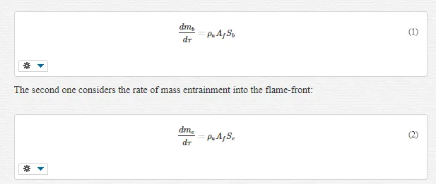
Gillespie and co-workers provide a useful review of those aspects of laminar and turbulent flame propagation, which are relevant to SI engines combustion [8]. Similarly to laminar-like combustion taking place in a quiescent environment, two main definitions of time-based combustion rate can be proposed for turbulent combustion. The first one relates to the rate of formation of burned products:
IN-CYLINDER MOTION FIELD AND EFFECTS ON COMBUSTION
Although the mean charge velocity in an engine cylinder may have an effect on the initial rate of combustion, by distorting the developing flame kernel and, possibly, by increasing the available burning surface [14], the main mechanism of combustion enhancement is turbulence.
Modern-design gasoline engines typically have 4 valves per cylinder, 2 intake and 2 exhaust valves. The use of two intake valves, which gives symmetry of the intake flow about the vertical axis, generates a mean cylinder motion called tumble, or vertical or barrel swirl, an organised rotation of the charge about an axis perpendicular to the cylinder axis. The strength of a tumbling flow is measured by means of a non-dimensional number called tumble ratio, defined as the ratio between the speed of the rotating bulk-flow and the rotational speed of the engine. The tumbling mean flow has been observed to promote combustion [15, 16] through turbulence production towards the end of the compression stroke. As the flow is compressed in a diminishing volume, the rotating vortices that make up the tumbling flow tend to break down into smaller structures and their kinetic energy is gradually and partially converted in turbulent kinetic energy. Whether the turbulence intensity is actually rising during compression (and at the start of combustion) would be dictated by the concurrent rates of turbulence production and natural viscous dissipation [17]. Although the literature is somewhat unclear on this specific topic, increased tumble ratio has been also reported to improve the cyclic stability and extend the running limits for lean or diluted mixtures [15, 18].
Theories have been developed which ascribe importance to additional turbulence generated inside the unburned region ahead of the reaction-front, by the expanding flame. None of them has been confirmed by direct observations and their validity has been always inferred by means of comparisons between models predictions and experimental data. Tabaczynski and co-workers [23, 24] advance the so-called eddy rapid distortion theory according to which the individual turbulence eddies experience fast isentropic compression, in such a way that their angular momentum is conserved. They conclude that due to this interaction the turbulence intensity increases and the length scale reduces, respectively, during the combustion process. Hoult and Wong [25], in a theoretical study based on a cylindrical constant-volume combustion vessel, apply the same rapid distortion theory to conclude that the turbulence level of the unburned gas depends only on its initial value and the degree of compression due to the expanding flame. An interesting fit of experimental data to inferred combustion-generated turbulence intensity is due to Groff and Matekunas [12].
VARIABLE VALVE ACTUATION MECHANISMS
The most commonly stated reason for introducing Variable Valve Actuation systems in SI engines is to raise the engine brake torque and achieve improvements in its variation with engine speed, especially at low speed (including idle conditions) and at the high end of the engine speed range. A second coexistent reason is to reduce the exhaust emissions, especially nitrogen oxides, but also unburned hydrocarbons [26]. Today many modern engines are equipped with VVA technology because measurable improvements can be gained in fuel consumption and efficiency over wide ranges of operating conditions, including part-load conditions. Efficiency improvements are a direct consequence of a reduction in pumping (intake throttling) losses. At low to medium load, variable valve strategy, in particular the extension of the valve overlap interval (between the Intake Valve Opening and Exhaust Valve Closing), exerts a strong influence upon the amount of burned gas recirculated from one engine cycle to the following one. This amount, or more specifically the so-called dilution mass fraction, has a profound influence upon combustion rates and duration. Combustion control strategies which aim at improved efficiency across the whole range of engine speeds and loads must carefully consider the extent to which the burning characteristics may be modified by VVA.
OVERVIEW OF VVA MECHANISMS
The development of VVA mechanisms started in the late 1960s and the first system was released into production in 1982 for the USA market, prompted by tightening emissions legislation [26]. The mechanism was a simple two-position device, which reduced the valve overlap at idle conditions, improving combustion stability and hence reducing the noxious emissions. Very different objectives, in particular the increase of the brake torque output at both ends of the engine speed range, induced a second manufacturer to develop a VVA system for small-capacity motorcycle engines. Released also in the early 1980s, the system worked by simply deactivating one inlet and one exhaust valve per cylinder at engine speeds below a fixed limit, achieving better mixing and greater in-cylinder turbulence as the available inlet flow area was reduced. A better understanding of the potential advantages in fuel efficiency has prompted, in recent years, an increased interest in VVA technology and most major manufacturers now produce engines with some form of VVA. Most systems presently in use allow continuous variable camshaft phasing; some complicated mechanisms are capable of switching cams to gain the benefits of different valve lifting profiles. From 2001 at least one manufacturer incorporated a variable valve lift and phase control mechanism into the first production engine that featured throttle-less control of engine load [27]. The amount of fresh air trapped into the cylinder is controlled solely by appropriate Intake Valve Closing strategy, removing the need for throttling and the associated pumping losses. Variable lift serves as a means of controlling the air induction velocity and ultimately the level of in-cylinder turbulence.
Ahmad and co-workers [28] classify the VVA systems into five categories depending on their level of sophistication. The most complicated devises are classified in category 5, capable of varying valve lift, opening durations and phasing, independently of each other for both intake and exhaust valve trains. Despite the potential advantages, mechanical systems in category 5 tend to be expensive, physically bulky and complicated. The mechanism used by the Author for the experimental work reported in the following sections is classified in category 3, as it allows continuous and independent variable phasing of intake and exhaust valve opening intervals, with fixed valve lifting profiles. This system is usually called Twin Independent-Variable Valve Timing. The Twin Equal-VVT system represents a simplification of the TI-VVT, where both camshafts are phased simultaneously by equal amounts.
VVT STRATEGIES AND INFLUENCE ON CHARGE DILUENT FRACTION
By means of multiple combinations of intake and exhaust valve timings, the TI-VVT system allows the identification of optimal operating strategies across the whole range of engine speed and load operating conditions. Early Intake Valve Opening timings produce large valve overlap interval and increase charge dilution with burned gas. Late IVO timings lead to increased pumping work, but may show an opposite effect at high engine speed where volumetric efficiency gains can be achieved by exploiting the intake system ram effects [6]. If the valve motion profiles are fixed, changes to IVO are reproduced by those to IVC, with significant effects on mass of fresh charge trapped, hence on engine load, and measurable changes in pumping losses. Early IVC controls engine load by closing the inlet valve when sufficient charge has been admitted into the cylinder. Reductions in Brake Specific Fuel Consumption of up to 10% have been observed with early IVC strategies [29, 30]. Recent studies by Fontana et al. [31] and by Cairns et al. [32] show similar reductions in fuel consumption, but explain these referring to the displacement of fresh air with combustion products during the valve overlap interval, which reduces the need for throttling. The Exhaust Valve Opening strategy would be dictated by a compromise between the benefits of the exhaust blow-down (early EVO) and those associated to a greater expansion ratio (late EVO). At high speed and load conditions, late EVC exploits the benefits of the ram effect, which may assist in the combustion products scavenging process. The exhaust valve strategy also contributes to the process of mixture preparation at all engine conditions, by trapping burned gases in the cylinder (early EVC) or by backflow into the cylinder when intake and exhaust valves are overlapping (late EVC).
Focusing on preparation of the combustible mixture and subsequent combustion process, the level of charge dilution by burned gas is the single most influential quantity, which is heavily varied using variable valve timing. Charge dilution tends to slow down the rate of combustion by increasing the charge heat capacity, ultimately reducing the adiabatic flame temperature. Charge dilution tends to increase with increasing valve overlap, particularly under light-load operating conditions when intake throttling produces a relatively high pressure differential between the exhaust and intake manifolds. This promotes a reverse flow of exhaust gas into the cylinder and intake ports. The recycled gas forms part of the trapped charge of the following engine cycle. There is a strong degree of interaction between the level of combustion products within the newly formed mixture and engine speed and load. Increasing speed shortens the duration of the valve overlap in real time, while increasing load raises the pressure-boundary of the intake system limiting the recirculating hot flows. At high speed and load conditions the increase of charge dilution with increasing valve overlap is limited.
CHARGE DILUTION MASS FRACTION – DEFINITIONS AND MEASUREMENTS
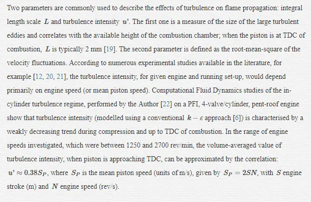
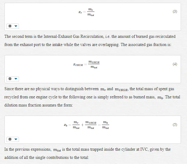
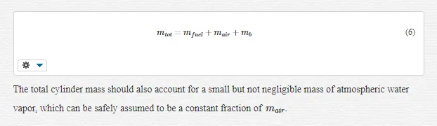
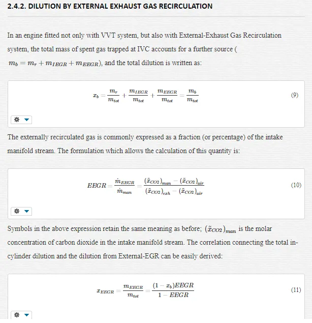
In the case of a gasoline engine fitted with VVT system, the dilution mass fraction is the sum of two different terms. The first one, properly named residual gas fraction, is associated with the amount of burned gas remaining inside the combustion chamber when the piston reaches the TDC of the exhaust stroke. If the exhaust valve closes before TDC, then the residual mass fraction would be given by the amount of burned gas trapped inside the cylinder at EVC. In symbols, the residual mass fraction is written as:
MEASUREMENTS OF DILUTION
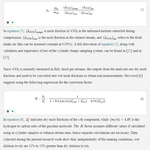
Methods to measure the cylinder charge diluent fraction are usually divided into two main categories: invasive or in situ techniques, and non-invasive. Invasive techniques, such as Spontaneous Raman Spectroscopy and Laser Induced Fluorescence, require physical modifications to the engine, likely interfering with the normal combustion process [33]. The experimental data presented in the following sections have been collected using a non-invasive in-cylinder sampling technique, which entails the extraction of a gas sample during the compression stroke of every engine cycle, between IVC and Spark Timing. The small extracted gas stream, controlled via a high-frequency valve, is passed through a first GFC IR analyser, which can work reliably at low flow rates, to yield carbon dioxide molar concentrations within the cylinder trapped mass. A second GFC IR analyser is used to measure exhaust
CO2CO2
, at the same time. Dilution mass fraction is calculated exploiting the readings from the two analysers, with the expression:
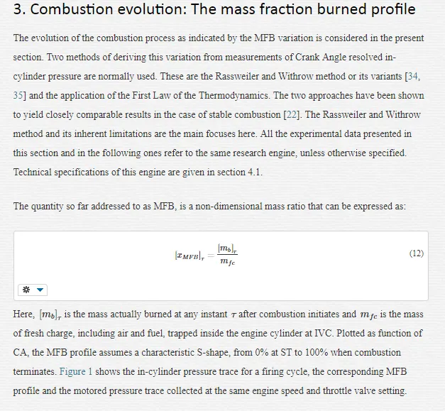
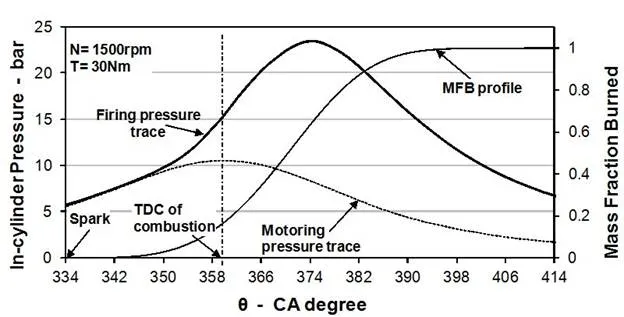
During the early flame development, that in the case of figure 1 begins with the spark discharge at 26 CA degrees BTDC, the energy release from the fuel that burns is so small that the pressure rise due to combustion is insignificant; firing and motoring pressure traces are, therefore, coincident. During this period, over about 13 CA degrees, the MFB rises very slowly. At the end of this stage an amount of charge as small as 1% has burned. During the second phase, the chemical energy release, from a stronger rate of burning, gives rise to the firing-cycle pressure trace. After peak pressure, that falls in this case at 15 CA degrees ATDC, when there is already an extensive contact between flame surface and cylinder walls, the MFB approaches 100% with progressively decreasing slope.
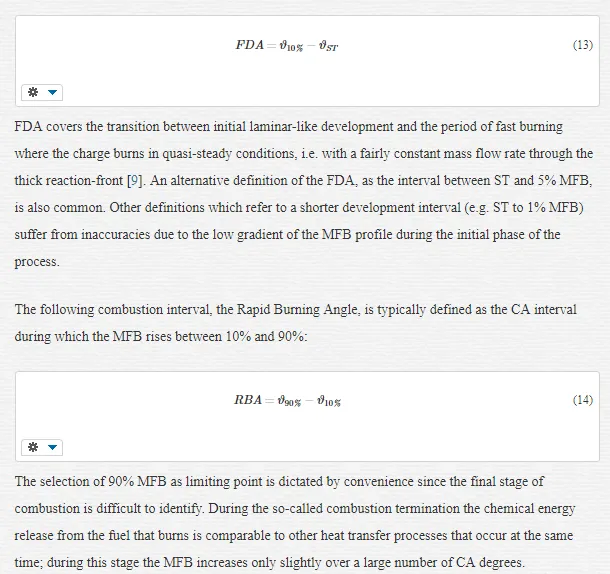
The MFB profile provides a convenient basis for combustion characterisation, which divides the combustion process in its significant intervals, flame development, rapid burning and combustion termination, in the CA domain. The initial region of the curve, from the spark discharge to the point where a small but identifiable fraction of the fuel has burned, represents the period of flame development. It is common to find the Flame Development Angle defined as the CA interval between ST and 10% MFB:
POLYTROPIC INDEXES AND EOC CONDITION FOR MFB CALCULATION
The method discussed above provides a robust platform to extract combustion evolution information from sensors data which are routinely acquired. Nevertheless, its accuracy is questionable as necessary constrains such as the EOC are not easily identifiable, and because it accounts for heat losses to the cylinder walls only implicitly, by selecting appropriate polytropic indices for compression and expansion strokes.
In theory, the polytropic index which figures in equation (17) should change continuously during combustion. However, this is not practical and an easier strategy of indices determination must be adopted. In the work presented here, two different values of the polytropic index are used for intervals in the compression and power strokes, respectively. The evaluation of the MFB curve proceeds by successive iterations, until appropriate values of the polytropic indexes, in connection with the determination of EOC, are established. The sensitivity of pressure increments to these indices increases with pressure and then is emphasized after TDC, when the in-cylinder pressure reaches its maximum. While the sensitivity of the MFB profile to the compression index is relatively low, the selection of the expansion index is more important. During compression the unburned mixture roughly undergoes a polytropic process that begins at IVC. In this work the polytropic compression index is calculated as the negative of the slope of the experimental [log V, log P] diagram over 30 consecutive points before ST, and maintained unvaried up to TDC. During the expansion stroke the polytropic index varies due to several concurrent phenomena, including heat transfer, work exchange and turbulence variation. In theory, it increases approaching an asymptotic value just before EVO. As suggested by Karim [37], the EOC associates the condition
ΔPc=0ΔPc=0
with an expansion index which settles to an almost constant value. Provided a reasonable condition is given to determine the EOC, the correct expansion index would be the one that, when combustion is over, maintains the MFB profile steadily at 100% till EVO: the zero combustion-pressure condition [35]. In this work, the expansion index is estimated with an iterative procedure where, starting from a reference value (e.g. 1.3), the index is progressively adjusted together with the EOC, until the MFB profile acquires a reasonable S-shape, which meets the requirement of the zero combustion-pressure condition. Several methods are reported in the literature to determine the EOC; the first negative and the sum negative methods, for example, assume that EOC occurs when one or three consecutive negative values of
ΔPcΔPc
are found. In this work, the combustion process is supposed to terminate when
ΔPcΔPc
becomes a negligible fraction (within 0.2%) of the total pressure increment
ΔPΔP
for 3 CA-steps consecutively.
OTHER METHODS OF ESTIMATION OF THE EXPANSION INDEX
Other methods have been proposed for the evaluation of
nexpnexp
. One calculates the index as the slope of the log-log indicator diagram over narrow intervals before EVO. Although this approach avoids the EOC determination, experimental results show that the calculations are sensitive to the chosen interval and, in general, combustion duration is overestimated. As an improvement to this method,
nexpnexp
has been calculated as the value that gives average
ΔPcΔPc
equal to zero after combustion terminates, satisfying the zero combustion-pressure condition [35]. Again, this approach seems to be sensitive to the interval over which the average
ΔPcΔPc
is evaluated, reflecting pressure measurements noise and the fact that often
nexpnexp
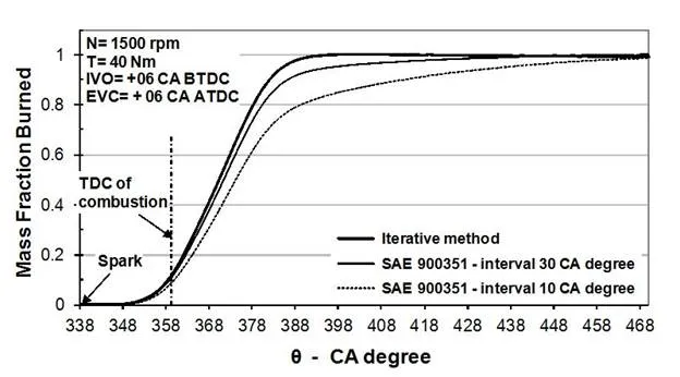
does not settle properly before EVO. Figure 2 directly compares three different methods of expansion index determination for engine speed of 1900 rev/min and torque of 40 Nm (similar results are obtained at different operating conditions): with the view that the iterative method of
nexpnexp
estimate yields accurate MFB characteristics (which, for stable combustion, are consistently similar to those from thermodynamics models [22]), the modification proposed in [35] tends to overestimate combustion duration during the rapid stage and especially during the termination stage, with the effect of delaying the EOC. The method for estimating the expansion index is crucially important as different methods may cause over 40% variation in the calculated RBA.
ESTIMATED ERRORS IN THE MFB PROFILE
The calculated burning characteristics of an engine, including the MFB profile, may be affected by measurements and calculation errors. Most of the potential inaccuracies are associated with the determination of the absolute in-cylinder pressure. The adoption of ensemble-averaged pressure trace, which as in the present work should be based on the acquisition of a minimum of 100 individual cycles [38], is beneficial to diminish the cyclical dispersion errors (inter-cycle pressure drift) [39] and signal noise. The major source of cylinder pressure error is indeed associated with thermal-shock and can be accounted for in terms of short-term or intra-cycle pressure drifts. Pressure sensors do not measure absolute pressure and the sensor signal need referencing to a known value. Since thermal-shock is driven by combustion, it would be preferable to perform cylinder pressure referencing when the artificial variability due to temperature changes is at a minimum, a circumstance which is likely to occur at the end of the intake stroke [40]. Nevertheless, the thermally induced drift persists throughout the whole engine cycle, assigning uncertainty to the experimental measurements. Payri et al. [39] account for a value of pressure accuracy of ±0.15 bar, estimated as maximum pressure difference at BDC of induction. Studies carried out by the Author [22] have shown that a value of intra-cycle pressure drift (calculated as difference between transducer BDC outputs at the beginning and at the end of single cycles) of ± 0.1 bar (with standard deviation of 0.055 bar) represents a realistic average estimate of the potential inaccuracy of the in-cylinder pressure.
When MFB profiles are built applying the Rassweiler and Withrow method to ensemble-averaged in-cylinder pressure records, at least two sources of errors can be considered: pressure measurements inaccuracy, but also the consequential polytropic compression index variation. Expansion index and EOC location are also affected by pressure variation but, if the iterative optimisation technique described above is used, these cannot be enumerated among the causes of uncertainties. The compression index variation is a linear function of the pressure variation at BDC of induction, almost independently of engine speed and load. A variation of +10% in BDC pressure induces a reduction of the compression index of about -1.5% [22]. Further studies on the effects of pressure drift (used as an offset) on the MFB profile, have shown that the region mostly affected is the flame development interval between ST and 10% MFB. For a pressure offset of ±0.1 bar, typical values of MFB percentage variation are likely to be around ±6% at 10% MFB for low engine load (IMEP = 2.5 bar); the error reduces proportionately at increasing load (typically ±1.5% at 10% MFB for IMEP = 6 bar). After 10% MFB, the MFB variation reduces consistently, reaching very small values, perhaps 1% or 0.5%, at 90% MFB. The error study by Brunt et al. [41] shows similar nature and magnitude of errors.
The effects of operating variables on combustion
The strength and duration of combustion in a given engine depend on a range of operating variables and, as stated in the beginning, the number of these tends to increase as technology advances. Understanding the connection between operating variables and burn rate characteristics is fundamental as the latter govern pressure development, spark timing requirements and, ultimately, work output and engine efficiency. The present section explores the results of an experimental research work carried out by the Author with the aim of enhancing the knowledge of how engine variables influence the progression of combustion in a modern engine featuring VVT system [42]. Conditions investigated covered light to medium engine load and speed, representative of urban and cruise driving conditions.
EXPERIMENTAL METHODOLOGY
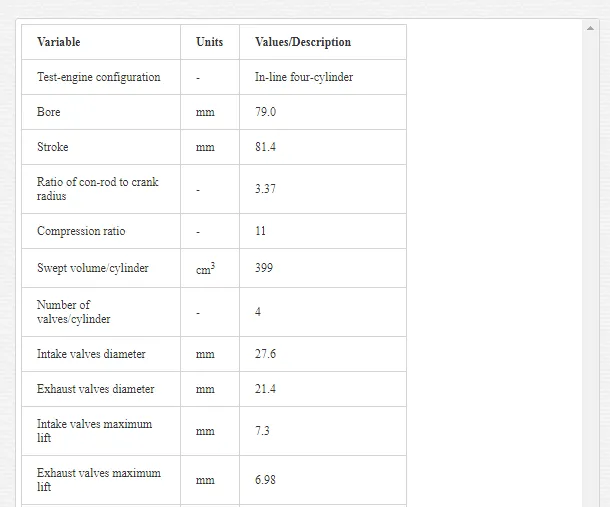
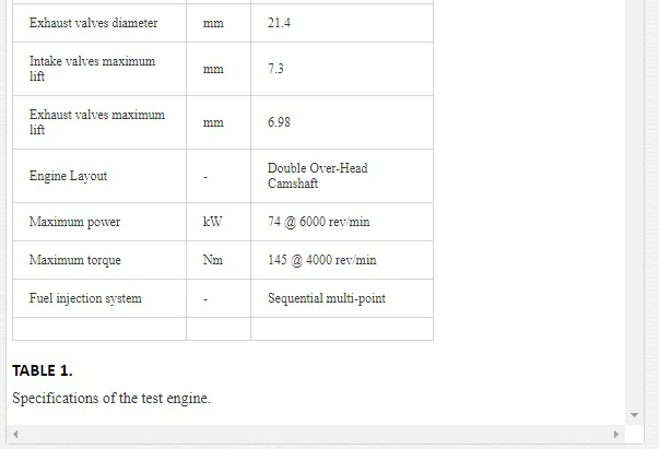
The test engine used in this work is a 1.6 litres, 4-cylinder, 4-valve/cylinder, PFI, SI engine, fitted with independent intake and exhaust valve timing control (TI-VVT) and central spark, pent-roof combustion chamber geometry. The technical details of the engine are summarised in Table 1. Engine testing was carried out under fully-warm, steady-state operating conditions and combustion was always kept stoichiometric, a requirement for high efficiency of 3-way catalytic convertors under most operating conditions. The air-to-fuel ratio was measured using a universal exhaust gas oxygen sensor and checked carrying out carbon and oxygen balances on the exhaust gases. The fuel used was grade 95 RON gasoline. Running conditions covered engine speed between 1500 and 3500 rev/min, IMEP between 2 and 7 bar, and spark ignition timing between 35 and 8 CA degrees BTDC.
The valve overlap, which controlled the diluent fraction via internal-EGR, was changed either by changing the EVC at constant IVO timing, or by changing the IVO at constant EVC timing. Timings here, as in the rest of the chapter, are given in terms of Crank (not Cam) Angles. The default EVC timing was +6 CA degrees ATDC, and the default IVO timing was +6 CA degrees BTDC. EVC sweeps covered the range -14 to +36 CA degrees ATDC, whereas IVO sweeps covered the range -24 to 36 CA degrees BTDC. The resulting overlap intervals varied from -20 (negative values actually denote IVO and EVC events separation, i.e. the exhaust valve closes before the intake valve opens) to +42 CA degrees. The diluent fraction, determined by sampling the cylinder charge during the compression stroke as explained in section 2.4, varied in the range 6 to 26% of the total trapped mass. An inter-cooled external EGR system was also fitted to the test engine to gain a certain degree of control over the charge dilution level, independently of the valve timing setting. The same system allowed running separate experiments where the changes brought about by the temperature of the recycled gases were observed.
A piezo-electric pressure transducer was installed flush-mounted in one cylinder to acquire in-cylinder pressure variation with 1 CA degree resolution. Ensemble-averaged values of pressure, calculated over batches of 100 consecutive cycles, were used to evaluate the MFB characteristics with the Rassweiler and Withrow methodology. The application details and limitations associated to this have been discussed in section 3.1. Values of combustion duration (in particular, FDA and RBA) were extracted from these and correlated with the relevant operating variables. The following sub-section explores how combustion duration varies as a result of changes to the valve overlap interval. An investigation on the influence of engine operating variables, varied in isolation at fixed valve timing setting, is also presented.
INFLUENCE OF VALVE TIMING ON COMBUSTION DURATION
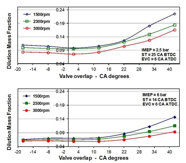
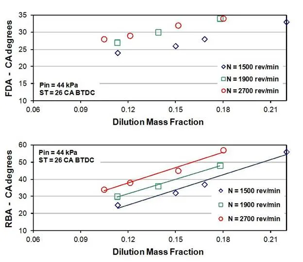
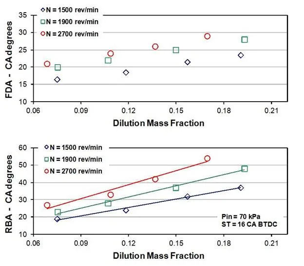
The influence of the valve timing strategy on dilution mass fraction and on the duration of combustion is presented here. As discussed in section 2.3.2, valve timing exerts a strong influence on mixture preparation by altering the amount of exhaust gas internally recirculated from one engine cycle to the following one. Dilution mass fraction measurements as a function of valve overlap are presented in figures 3 and 4 for three representative engine speeds, at each of two fixed engine loads (kept constant by acting on the throttle valve position) and spark timings. The spark ignition advance was kept unvaried at 25 CA degrees BTDC for the low load cases and at 14 CA degrees BTDC for the high load cases. The valve timing setting was changed as described in section 4.1; figure 3 refers to fixed EVC timing and figure 4, which shows similar distributions, refers to fixed IVO timing. Levels of dilution are greatest at low-load, low-speed conditions, because of a stronger exhaust gas back-flow when the intake and exhaust valves are overlapping. As expected, dilution mass fraction is an increasing function of valve overlap and, across regions of positive overlaps, it rises at increasing rate as the overlap value increases. For small values of either positive or negative valve overlap, the dilution fraction is relatively constant. When the valve overlap grows negatively (producing wider valve events separation), relatively small increments in dilution are due to early EVC, which has the effect of trapping more residuals, or to late IVO, which reduces the amount of fresh air trapped inside the cylinder.
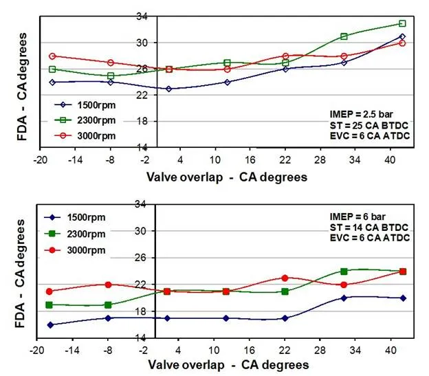
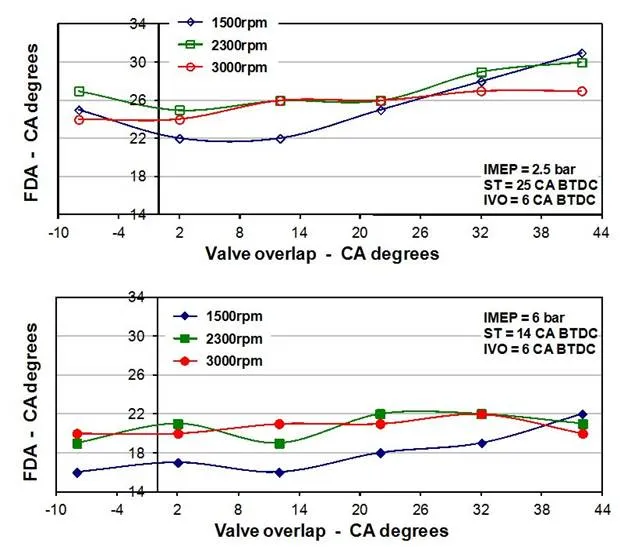
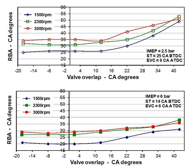
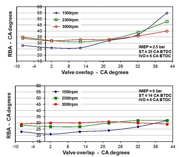
Representative results for the 0 to 10% MFB duration (FDA) are given in figures 5 and 6; those for the 10 to 90% MFB duration (RBA) are given in figures 7 and 8. The burn angles are plotted for three engine speeds and two levels of IMEP and spark advance. Both FDA and RBA increase consistently with increasing values of positive valve overlap. The increase in RBA is more pronounced than that in FDA, and proportionately greatest at low-load conditions (2.5 bar IMEP). The variations with overlap are similar for fixed intake and fixed exhaust timings, indicating that overlap phasing about TDC is not critical and the influence on combustion is exerted primarily through the overlap extension. The plotted trends are similar at all three engine speeds considered, with a small offset which reflects the inherent increase in burn duration as the speed increases. For small positive overlaps and for negative overlaps the burn angles do not show evident correlation with valve overlap. In these regions, the back-flow into the cylinder is reduced or does not occur at all, indicating that dilution mass fraction is the main cause of combustion duration alterations. Figure 5 to 8 show data which refer to operating conditions at which some variations of combustion duration was actually found. For running conditions exceeding about 6 bar IMEP and 3000 rev/min, combustion duration is almost independent of the valve timing setting.
The analysis of figures 3 to 8 suggests that the influence of dilution accounts for most of the variation in the rate of combustion with variable valve overlap. The effect of valve timing exerted through modifications to bulk motion and turbulence was not apparent in the data. Plots of RBA against dilution (not included here, but available in [42]) depict linear trends with gradients of variation only slightly biased towards greater engine speeds, and also independent of the valve overlap phasing. Similar conclusions for part-load running conditions and intake valve-only variations have been drawn by Bozza et al. in [43], whereas Sandquist et al. [44] observed that the linearity between burn angles and charge dilution held only for fixed phasing, indicating that a dependence upon engine design is possible. The FDA also increases linearly with dilution mass fraction, though at a much weaker rate.
INFLUENCE OF OTHER OPERATING VARIABLES ON COMBUSTION DURATION
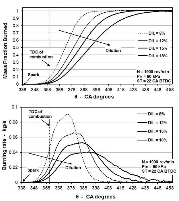
The influence of charge dilution upon rate and duration of combustion was explored also by means of separate tests carried out at fixed valve timing setting, to minimize any potential underlying influence on combustion, and using variable amounts of external EGR. Valve timing was set at default configuration, i.e. IVO = +6 CA degrees BTDC, and EVC = +6 CA degrees ATDC. Figure 9 illustrates the general effect of increasing charge dilution on MFB and burning rate characteristics, for fixed engine speed of 1900 rev/min and fixed intake pressure of 60 kPa. As expected, increasing dilution tends to reduce the strength of combustion, as indicated by the peak burning rate in kg/s, and stretches its duration over larger CA intervals for both the development and the rapid burning stages. Representative results for the variation of FDA and RBA with dilution mass fraction for three engines speed, at each of two engine loads and spark advances, are given in figures 10 and 11. Both combustion intervals are seen to increase linearly at a rate which is essentially independent of engine load and spark timing [45]. As discussed in the previous section, the gradients of these linear correlations, particularly for the RBA, are only slightly biased towards greater engine speeds, as a result of extending combustion further along the expansion stroke, into regions of lower temperature and pressure. When the level of dilution is varied by means of cooled external-EGR, combustion duration increases at a slightly higher rate than the case of dilution changes from increasing valve overlap. This is explained considering that charge temperature and charge density variations, which occur at the same time as dilution changes when the valve timing is modified, tend to moderate the influence of dilution on burn rate.
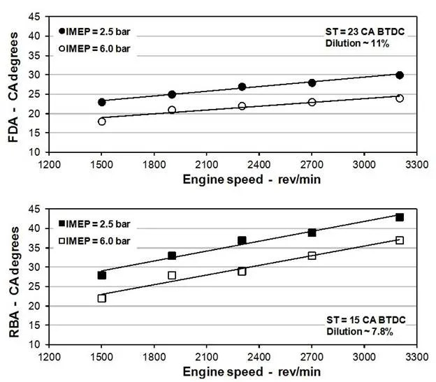
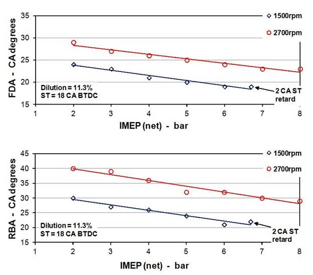
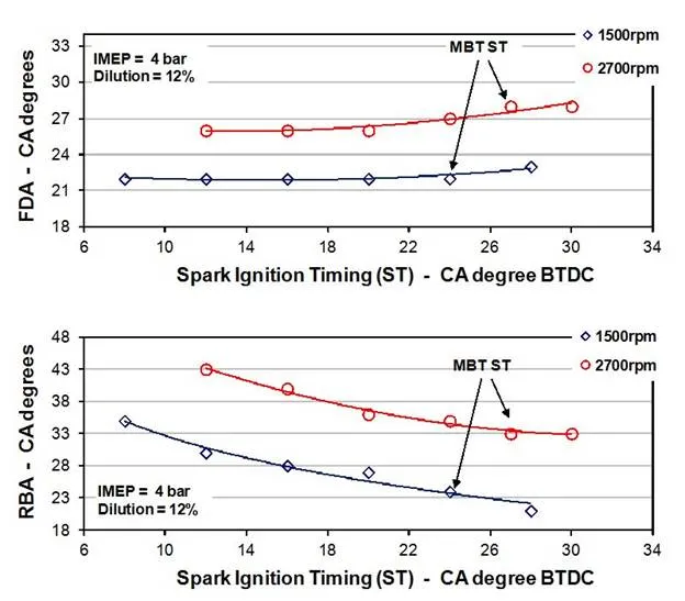
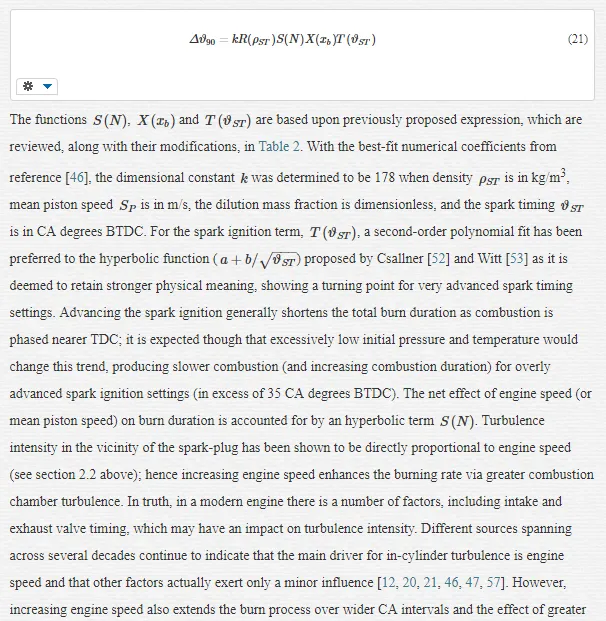
Figures 12 to 14 illustrate the effects of engine speed, load and spark advance on combustion duration. Experimental data were again recorded under default valve timing setting, and the dilution level was kept unvaried by using appropriate rates of external EGR. In figure 12, the FDA and the RBA increase almost linearly with increasing engine speed, with gradients of variation which appear independent of engine load. The RBA increases more rapidly than the FDA because, as discussed above, greater engine speed would stretch the rapid stage of combustion further into the expansion stroke. Engine speed, as discussed in section 2.2, is directly proportional to turbulence intensity and therefore greater engine speed would lead to an augmented rate of combustion by means of increased unburned gas entrainment into the propagating flame front. However, increasing speed extends the burn process over wider CA intervals and the effect of greater turbulence intensity is only to moderate such extension. Doubling the engine speed between 1500 rev/min and 3000 rev/min stretches FDA by about 1/3 and RBA by 1/2. Figure 13 shows that FDA and RBA decrease linearly when plotted as a function of engine load, in terms of IMEP, at constant level of dilution mass fraction. Both burn angles decrease linearly also with increasing intake manifold pressure. The RBA decreases at an average rate of 2.7 CA degrees per 10 kPa increase in intake manifold pressure. The FDA decreases at a rate which is approximately half of the one calculated for the RBA. Some representative results concerning the variation of the burn angles with the degree of ST advance, at fixed dilution, are illustrated in figure 14. As the ignition timing is advanced towards the MBT setting, combustion initiates earlier in the compression stroke, i.e. at lower temperatures and pressures. Under the influence of these less favourable conditions for flame development, the FDA increases slightly. At the same time RBA, which cover the bulk of combustion duration, tends to decrease as the overall combustion phasing improves. The trends in figure 14 extend to STs more advanced than the MBT values, but the degree of over-advance was limited to 3–4 CA degrees to avoid the inception of knock and this was too small to establish any turning point.

Simplified combustion modelling
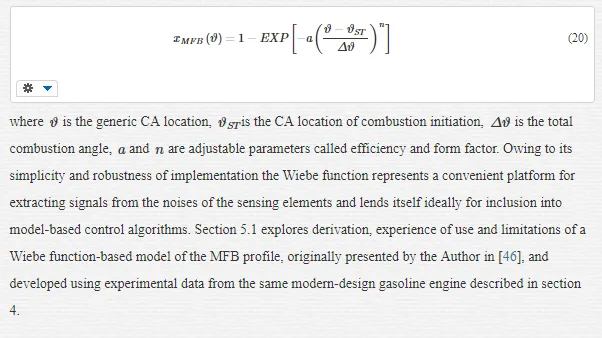
The ability to describe analytically the charge burn process in SI engines, capturing the details of the most relevant influences on this, is essential for both diagnosis of performance and control requirements. The empirical combustion models that enable just the above ability are usually called non-dimensional or zero-dimensional models, because they do not incorporate any explicit reference to combustion chamber geometry and flame front propagation. Such approaches typically output the burn rate or the MFB profile in the CA domain and require several stages of calibration by fitting real engine data to appropriate analytical functions. One of the most widely used methods in engines research is to carry out curve fits of experimental MFB curves to describe the combustion evolution via a Wiebe Function,
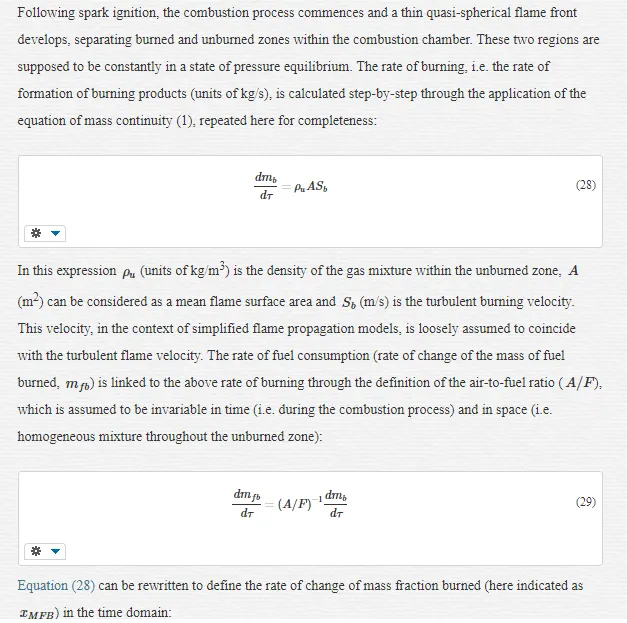
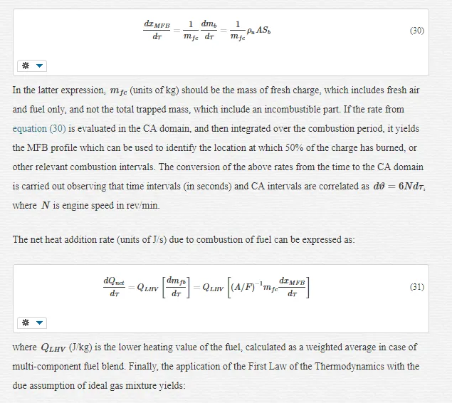
A different type of combustion models are the so-called phenomenological or quasi-dimensional models. These require spatial subdivision of the combustion space into zones of different temperature and chemical composition (two zones, burned and unburned, in their simplest version) and are often used to evaluate both combustion of fuel and associated pollutant formation. Phenomenological models are based on more fundamental theoretical principles, hence they should be transportable between engines of different size and geometry. Nevertheless, these models also require some form of calibration using real measurements. Recent published work by Hall et al. [47] and by Prucka et al. [5] offers examples of relatively simple phenomenological flame propagation and entrainment models, suited for inclusion into fast-execution ST control algorithms, to ensure optimal phasing of the 50% MFB location (i.e. 7 or 8 CA degree ATDC) and improve engine efficiency and fuel economy. In these models, the instantaneous rate of combustion is calculated fundamentally, through some modifications of the basic equation of mass continuity
dmb/dτ=ρuASbdmb/dτ=ρuASb
. Section 5.2 illustrates one of these models, along with results which highlight the influence of relevant engine operating variables on combustion for a modern flexible-fuel engine.
COMBUSTION MODELLING USING THE WIEBE FUNCTION
One of the most comprehensive accounts of rationale and applications of the Wiebe function as a burn rate model is due to J. I. Ghojel, in his recent tribute to the lasting legacy of the Wiebe function and to the man behind it, Ivan Ivanovitch Wiebe [48]. The purpose of the original work by Wiebe was to develop a macroscopic reaction rate expression to bypass the complex chemical kinetics of all the reactions taking place in engine combustion. The result, which is typically based on a law of normal distribution representing the engine burning rate, is a very flexible function, heavily used in the last few decades to model all forms and modes of combustion, including compression and spark ignition, direct and indirect injection and homogeneous charge compression ignition combustion, with a range of liquid and gaseous fuels. An extensive survey on the implementation of the Wiebe function (as well as some mathematical modifications) has been also carried out by Oppenheim et al. [49]. Here the authors recognise the practical virtues of the function and its well-established use, but question its derivation, which is described as a gigantic leap from chemical kinetics of the exothermic reactions of combustion to the consumption of fuel.
METHODOLOGY
The aim of the investigation is to model the S-shaped MFB profile from combustion initiation (assumed to coincide with spark timing) to termination (100% MFB), using the independent parameters of the Wiebe function. The total burning angle is taken as the 0 to 90% burn interval,
Δϑ90Δϑ90
, preferred to the 0-99.9% interval used in other work (for example [50]) as the point of 90% MFB can be determined experimentally with greater certainty. Especially for highly-diluted, slow-burning combustion events the termination stage cannot be described accurately from experimental pressure records, as the relatively small amount of heat released from combustion of fuel is comparable to co-existing heat losses, e.g. to the cylinder walls [51]. For these reasons, using the
Δϑ90Δϑ90
rather than the
Δϑ99.9Δϑ99.9
as total combustion angle should ascribe increased accuracy to the overall combustion model. It can be demonstrated that, with the above choice of total combustion angle, the efficiency factor
aa
takes a unique value of 2.3026.
Δϑ90Δϑ90
and
nn
remain as independent parameters and curve fits to experimental MFB curves allow correlating these to measurable or inferred engine variables.
The experimental data used for model calibration have been collected using the research engine described in section 4.1. All tests were carried out under steady-state, fully-warm operating conditions which covered ranges of engine speed, load, spark advance and cylinder charge dilution typical of urban and cruise driving conditions. Data were recorded using always stoichiometric mixtures. Dilution mass fraction, determined from measurements of molar concentrations of carbon dioxide as indicated in section 2.4, was varied either via an inter-cooled external-EGR system or adjusting the degree of valves overlap via the computerised engine-rig controller. Intake and exhaust valve timing were varied independently to set overlap intervals from -20 to +42 CA degrees. The ranges of engine variables covered in this work are the same as those reported in section 4.1. The experimental database included in excess of 300 test-points. Data collected varying the valve timing setting were kept separately and used for purposes of model validation. MFB profiles at each test-point were built applying the Rassweiler and Withrow methodology to ensemble-averaged pressure traces. The FDA, 50% MFB duration (
Δϑ50Δϑ50
) and RBA were calculated from these curves, using a linear interpolation between two successive crank angles across 10%, 50% and 90% MFB to improve the accuracy of the calculations.
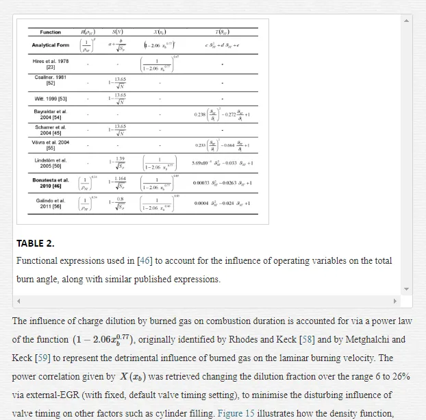
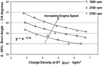
The combustion process in premixed gasoline engines is influenced by a wide range of engine specific as well as operating variables. Some of these variables, such as the valve timing setting, can be continuously varied to achieve optimum thermal efficiency (e.g. by improving cylinder filling and reducing pumping losses) or to meet ever more stringent emissions regulations (e.g. by increasing the burned gas fraction to control the nitrogen oxides emissions). There is some consensus in recent SI engine combustion literature upon the variables which are essential and sufficient to model the charge burn process in the context of current-design SI engines [23, 45, 50, 52, 53, 54, 55, 56]. For stoichiometric combustion, in decreasing rank of importance these are charge dilution by burned gas, engine speed, ignition timing and charge density. In the present work dilution mass fraction has been of particular interest as large dilution variations produced by both valve timing setting and external-EGR are part of current combustion and emissions control strategies.
MODELS DERIVATION
Empirical correlations for the two independent parameters of the Wiebe function, the total burn angle,
Δϑ90Δϑ90
and the form factor,
nn
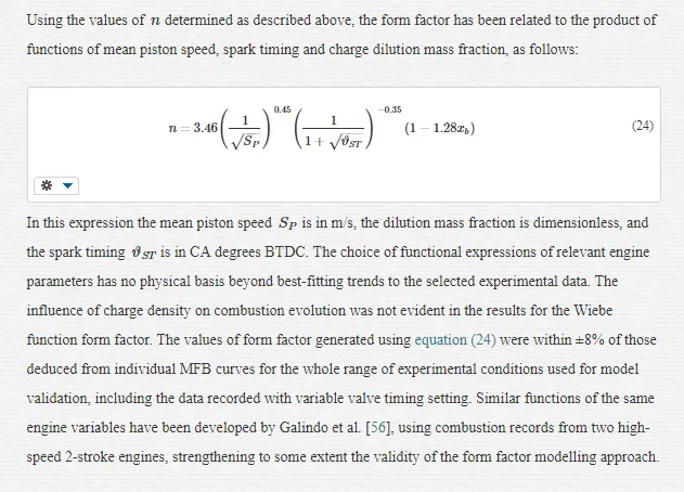
, have been developed carrying out least mean square fits of functional expressions of engine variables to combustion duration data. Whenever possible, power law functions were used in order to minimise the need for calibration coefficients. The choice of each term is made to best fit the available experimental data.
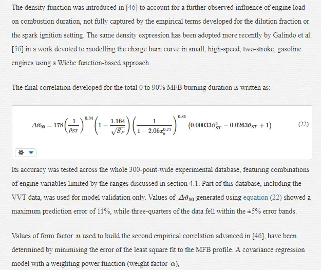
The 0 to 90% MFB combustion angle is expressed as the product of 4 functional factors, whose influence is assumed to be independent and separable:
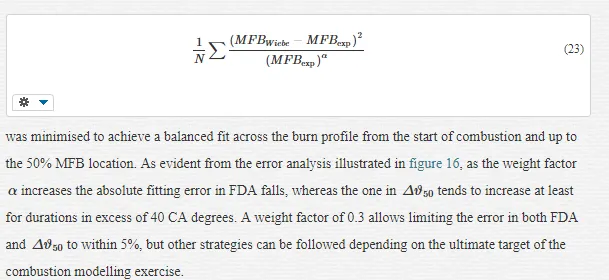
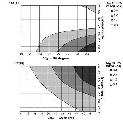
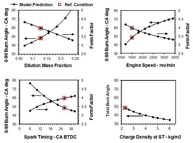
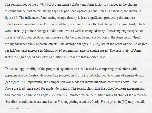
DISCUSSION OF RESULTS AND ACCURACY
Expressions for the 0-90% MFB angle and the form factor of the Wiebe function have been derived empirically to represent the burn rate characteristics of a modern-design SI engine featuring VVT. Four factors – dilution mass fraction, engine speed, ignition timing and charge density at ignition location, were used to describe the evolution of premixed SI gasoline combustion. The range of engine operating conditions examined covered a large portion of the part-load envelope and high levels of dilution by burned gas. Valve timing influences combustion duration mostly through changes in the levels of dilution and in-cylinder filling; the results show that these influences are captured by the proposed models. Other effects which might results from valve timing changes, such as the changes in turbulence level, appear to be secondary and no explicit account of these has been required [46, 47, 60].
Average errors in FDA, RBA and
Δϑ50Δϑ50
, calculated using the Wiebe function with modelled inputs, were in the region of 4.5%; maximum errors across the whole database were within the 13% error bands. This magnitude of uncertainty is typical of simplified thermodynamics combustion models applied to engines with flexible controls. Importantly, the analysis has shown that errors of magnitude up to 7% would be expected due to the inherent limitations of fitting a Wiebe function to an experimental MFB profile [46]. Further error analysis shows that the expected errors in the various combustion duration indicators are proportional to those in
Δϑ90Δϑ90
. Overestimates of the form factor increase the predicted FDA and reduce the RBA. The influence of
nn
upon
Δϑ50Δϑ50
is instead relatively small; this suggests the approach presented here may be applicable to combustion phasing control.
FLAME PROPAGATION MODELLING
As discussed previously, locating the 50% MFB event at 7 or 8 CA past TDC has been correlated to achieving best fuel efficiency in SI engine combustion. The recent work by Hall et al. [47] outlines a relatively simple, physics-based, quasi-dimensional flame propagation model capable of capturing the influence of variable valve timing, ethanol/gasoline blend ratio and other parameters relevant to modern SI engines, to provide estimates of the 50% MFB location and hence phase the combustion period most appropriately with respect to TDC. The model advanced by Prucka et al. [5] is similarly used for predicting best ignition timing in complex SI engine architectures (featuring not only VVT technology but also a charge motion control valve), but it is different in its logic as it relies on a simplified adaptation of the turbulent flame entrainment concept originally introduced by Blizard and Keck [61]. The present section introduces the reader to the first type of combustion models, which is less reliant on complex descriptions of fuel burning rate and turbulence regimes, and hence more readily implementable.
ASSUMPTIONS AND METHODOLOGY
Simplified flame propagation models tend to use readily available measurements from sensors and output estimates of ignition timing to achieve best efficiency for given engine running conditions. The basic inputs can be listed as follows:
· engine speed
· mass of fuel injected and ethanol/gasoline ratio
· equivalent ratio (or air-to-fuel ratio)
· spark timing and relative thermodynamic conditions (temperature, pressure and charge density)
· dilution mass fraction or charge characterization (masses of fresh air and burned gas trapped at IVC)
Charge dilution should be measured or estimated through gas exchange modelling, exploiting values for intake and exhaust manifold pressure as well as available cylinder volume at the IVO and at the EVC event. The exhaust manifold temperature appears in the calculations, weakening (due to the inherent slow response time of temperature sensors) the applicability of the approach to transient operation. In Hall et al. [47] the degree of positive valve overlap is considered directly responsible for the charge characterization, while modulation of valve lift and, more in general, changes of valve opening profiles, which may directly affect the level of turbulence, are not investigated.
The in-cylinder thermodynamic conditions at the time of ignition (ST) can be calculated assuming polytropic compression from IVC conditions:
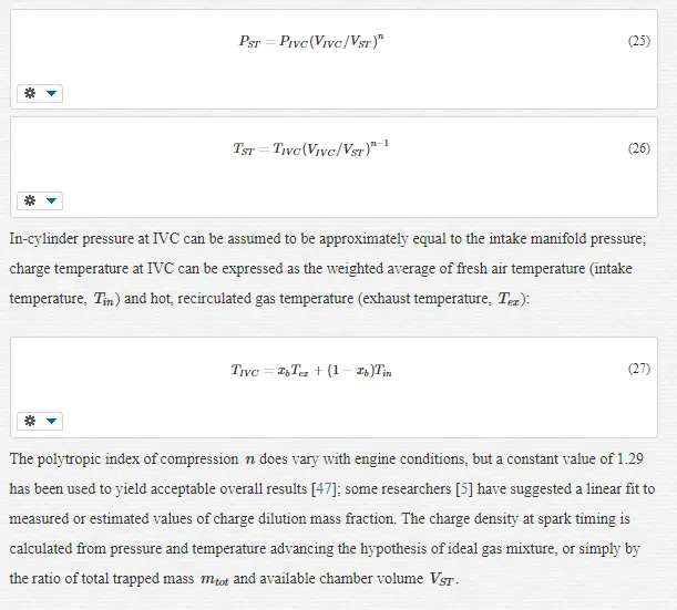
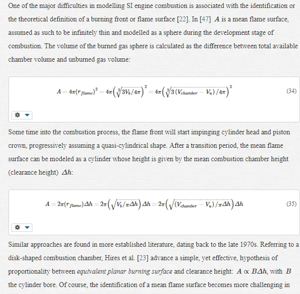
the context of modern combustion chamber geometries such as pent-roof shape chambers; nevertheless, the basic concepts to be adopted in the context of simplified quasi-dimensional combustion modelling remain valid. The topic of SI combustion propagating front, where a fundamental distinction is made between cold sheet-like front, burning surface and thick turbulent brush-like front, is complex and outside the scope of the present work; the interested reader is referred to some established, specialised literature [8, 11, 12, 13, 63].
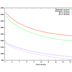
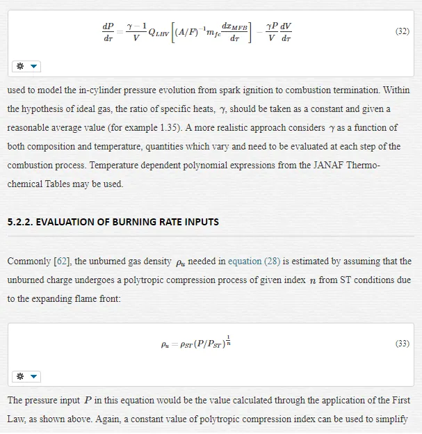
The turbulent burning or flame speed,
SbSb
, embodies the dependence of the burning rate on turbulence as well as on the thermo-chemical state of the cylinder charge. In time, these dependences have been given various mathematical forms, though all indicate that in-cylinder turbulence acts as an enhancing factor on the leading, laminar-like flame regime. The first turbulent flame propagation model was advanced in 1940 by Damköhler for the so-called wrinkled laminar flame regime [64]. The turbulence burning velocity was expressed as:
Sb=u’+SLSb=u’+SL
, where
u’u’
is the turbulence intensity and
SLSL
is the laminar burning velocity. An improvement on this model was proposed by Keck and co-workers [9, 11], showing that during the rapid, quasi-steady combustion phase the turbulent burning velocity assumes the form:
Sb≈auT+SLSb≈auT+SL
, where
uTuT
is a characteristic velocity due to turbulent convection, proportional to unburned gas density as well as mean inlet gas speed. In 1977 Tabaczynski and co-workers developed a detailed description of the turbulent eddy burn-up process to define a semi-fundamental model of the turbulent burning velocity [24].
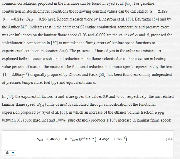
In [47] the turbulent flame velocity is given as the product of laminar velocity and a turbulence-enhancement factor. In line with the speed/turbulence association discussed above, this factor is expressed as a linear function of engine speed only [57, 65]:
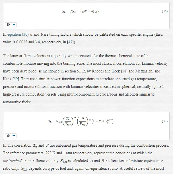
DISCUSSION OF RESULTS
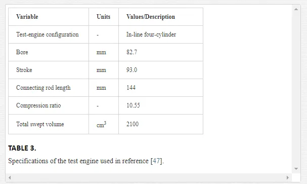
The flame propagation type models presented above are physics-based and hence, in principle, can be generalised to engines of different geometries. Through the definition of the laminar flame velocity, they enable accounting for two very relevant influences on combustion, i.e. the charge diluent fraction and the composition and strength of the fuel mixture. In spite of their simplicity, partly due to the range of assumptions taken, this type of control-oriented models has been demonstrated to capture the rate of combustion of modern SI engines with acceptable level of confidence. Hall et al. [47] validate the model using experimental records from a turbo-charged, PFI, flexible-fuel, SI engine, the specification of which are given in table 3.
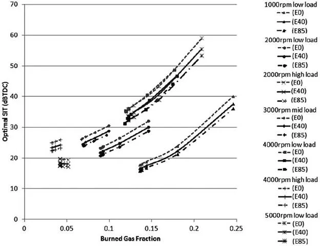
More than 500 test points were used, consisting of combinations of engine speed between 750 and 5500 rev/min, intake manifold pressure between 0.4 and 2.2 bar, ST between -12 and 60 CA degrees BTDC and valve overlap between -16 and 24 CA degrees (intake valve timing only). Four basic ethanol/gasoline blend ratios were tested, between E0 (pure gasoline) and E85 (0.85 ethanol and 0.15 gasoline, as volume fractions). In the vast majority of instances, the model predicted the duration of the interval between ST and 50% MFB (
Δϑ50Δϑ50
) with a maximum error of 10%. The influence of relevant engine parameters on combustion duration is summarized in figure 19. This shows the theoretical Spark Ignition Timing (SIT) which ensures optimal 50% MFB location (i.e. at 8 CA degrees ATDC), when variable amounts of charge dilution (here Burned Gas Fraction), and variable amounts of ethanol are used, at different engine operating conditions. The
Δϑ50Δϑ50
interval can be evaluated indirectly, as the interval between SIT and 8 CA degrees ATDC.
As expected, an increase in the diluent fraction determines a slower combustion process (i.e. wider
Δϑ50Δϑ50
) at all engine operating conditions, except at high engine load where the variation of the Burned Gas Fraction as a function of valve overlap is very limited. Conversely, the addition of ethanol to gasoline induces faster laminar flame speed and a stronger burning rate [65], reducing
Δϑ50Δϑ50
as a consequence. Increasing charge dilution necessitates more advanced theoretical ignition, whereas the ethanol content shows an opposite influence. An increase in dilution of 10 point percent requires about 25 CA degrees ignition advancement at low engine load. Increasing the ethanol content between E0 and E85 would reduce the required advancement between 3 and 6 CA degrees.
Conclusions
The present chapter explores the evolution of the combustion process in modern-design, premixed, gasoline engines, which feature the increasingly common technology of variable valve timing. The assessment of combustion rates and duration has been performed by looking at the effects of a set of significant engine operating variables, which were studied in isolation. The chapter also explores recently-proposed simplified thermodynamic combustion models, which can be in principle deployed within fast-execution control algorithms. The engine data used cover a large portion of the part-load envelope, reflecting typical urban and cruise driving conditions, but incorporate high load operating conditions enabling a more comprehensive evaluation of combustion. The results presented are relevant to port-fuel injection gasoline engines, which feature homogeneous SI combustion, but also to direct-injection gasoline engines, because these run in theoretically-homogeneous combustion mode for a large part of the operating envelope. Despite burn rates and duration are invariably a function of engine geometry, the data used throughout the study for combustion analysis and modelling refer to the very common modern-design of 4-valve pent-roof combustion chamber, which also ascribes relevance and generality to the findings.
In modern engine architectures, the analysis of combustion tends to be intrinsically rich in details and challenging, and the ability to identify the most influential variables is crucial. Four operating variables are deemed as essential and sufficient to model the charge burn process in the context of current-design SI engines; in decreasing rank of importance these are charge dilution by burned gas, engine speed, ignition timing and charge density. In the present work dilution mass fraction, which slows the burning rate by increasing the cylinder charge heat capacity, has been of particular interest as large dilution variations produced by both valve timing setting and external-EGR are part of current combustion and emissions control strategies. The second most relevant engine variable is engine speed; greater engine speeds stretch the burning process over increasing intervals in the CA domain, as well as having a direct marked influence upon the level of combustion chamber turbulence. Similarly to engine load, the spark timing determines the thermodynamic state of the mixture when combustion commences, as well as controlling combustion phasing across TDC. Charge density calculated at spark timing is taken as an indication of engine load or of the amount of trapped mass within the cylinder.
Especially at low to medium load, the valve timing strategy exerts a strong influence upon both engine breathing ability and amount of burned gas internally recirculated during the valve overlap interval. Combustion control strategies aimed at improved efficiency must carefully consider the extent to which the burning characteristics are modified by VVT. Owing primarily to the influence of charge dilution, both FDA and RBA increase consistently with increasing degree of positive overlap, though the increase in RBA is more pronounced, and proportionately greater as engine load is reduced. In the range of valve timings investigated (EVC and IVO were varied between -14 and 36 and between -24 and 36 CA degrees BTDC, respectively), the experimental data show that the influence on combustion duration is exerted primarily through the overlap extension, whereas the overlap phasing about TDC is not critical. At relatively high load and speed conditions, combustion duration is found to be virtually independent of the valve timing setting. The effect of valve timing exerted through modifications to bulk motion and turbulence is not apparent in the data.
When the level of charge dilution is varied in isolation, by using fixed valve timing and variable amounts of external-EGR, both FDA and RBA increase linearly with increasing dilution, and the variation of RBA is slightly biased towards greater engine speed as a result of extending combustion further into the expansion stroke. When engine speed is varied in isolation, both combustion angles are found to increase linearly with increasing engine speed, with gradients of variation which appear independent of engine load. When engine speed increases between 1500 and 3000 rev/min, FDA and RBA grow by about 1/3 and 1/2, respectively.
Functional expressions for the total combustion angle,
Δϑ90Δϑ90
, and the so-called form factor have been derived empirically as inputs of the Wiebe function to model the charge burn process of a premixed gasoline SI engine. The application of the model for
Δϑ90Δϑ90
yields average changes in the total burn angle of 10 CA degrees when dilution mass fraction increases by 5 point percent or engine speed increases by 800 rev/min. The maximum errors in FDA, RBA and
Δϑ50Δϑ50
, calculated using the Wiebe function with modelled inputs, were within 13%, which is typical of simplified combustion models applied to complex engine architectures. Importantly, the analysis has shown that errors of magnitude up to 7% would be expected due to the inherent limitations of fitting a Wiebe function to an experimental MFB profile. The error analysis also shows that the influence of the Wiebe function form factor upon
Δϑ50Δϑ50
is relatively small, suggesting the modelling approach presented may be applicable to combustion phasing control.
Straightforward methods of combustion modelling as the Wiebe function or simplified flame propagation models (also outlined in this chapter) lend themselves ideally for robust inclusion into feed-back or feed-forward combustion control algorithms. If appropriately calibrated, these models are able to capture the most relevant factors influencing the rate of combustion and may enable efficiency improvement also during transient or variable operation. The main issue with the application of such models comes from relying on accurate values of in-cylinder charge dilution. High frequency sampling and analysis of the quantity of burned gas within the combustible mixture cannot be performed. Faster indirect measurement techniques are currently being studied, but are still far from becoming established technology. Engine mapping work may allow the compilation of multi-level look-up tables where dilution mass fraction can be tabulated as a function of engine speed, load, as well as intake and exhaust valve timing setting; these tables can be used to yield model inputs during steady-state running, less so during variable operation when the boundary conditions determining the diluent fraction change on a cycle-to-cycle basis. Physical measurements can be replaced by charge dilution models, but compounding the uncertainties associated to the various models may compromise the validity of the general approach. The best alternative among the various possible methods of combustion control would be the one enabling measurable improvements in fuel economy over a representative drive-cycle and further studies are needed in this field.
Supported by a vast and efficient infrastructure, the SI engine running on gasoline fuels continue to power the vast majority of light-duty vehicles used today across the globe. Due to the present level of technological advancement, as well as to the ever more stringent emission regulations, the homogenous premixed mode of combustion remains the favourite choice for most production SI engines. The current scenario will not be altered easily, until new technologies and new alternative fuels become widely available and truly sustainable. In such a context, the investigation of gasoline premixed combustion, which in recent years is increasingly focusing on control strategy optimisation in high-degree-of-freedom engines, continues to be of paramount importance.