Constructors of gasoline engines are faced with higher and higher requirements as regards to ecological issues and an increase in engine efficiency at a simultaneous decrease in fuel consumption. Satisfaction of these requirements is possible owing to the recognition of the phenomena occurring inside the engine cylinder, the choice of suitable optimal parameters of the fuel injection process, and the determination of the geometrical shapes of the combustion chamber and the piston head. All these parameters indeed have a considerable impact on the improvement of gasoline engines performance, and they increase their efficiency.
The increase in the engine efficiency is basically the result of the change in the fuel supply method, that is by proper regulation of the petrol-air mixture composition depending on the rotational speed and load. This is why the lean mixture combustion in the gasoline engine. Further lowering of the temperature during the development of the fuel-air mixture, which is an outcome of the heat being taken away from the evaporated spout by the surrounding air, makes it possible to increase the compression ratio, which translates to the increase of the ideal efficiency.
With direct petrol injection system, is essential for increasing the efficiency at a simultaneous decrease of the toxic fumes emission and fuel consumption.
The first construction of the fuel supply system with electronically controlled direct injection system was introduced into batch production in 1996 by the Japanese Mitsubishi concern, in the Carisma model with the 4G93 GDI engine. The innovative solution made the disposed power and maximal moment grow by 10%, and the elementary fuel consumption fell by 20% in relation to the formerly used engine with indirect fuel injection system.
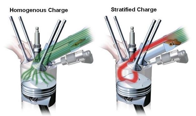
The improvement of the above mentioned parameters was possible owing to the implementation of the system of laminar lean fuel-air mixture combustion in the range of partial load and low to medium rotational speeds of the engine. The laminar load was created by the wall-guided fuel injection.
The injected fuel spout, with the proper angle of the crankshaft revolution during the compression stroke rebounces from the piston head and is directed towards the spark plug electrodes. The rapid development of internal combustion engines with direct petrol injection caused the introduction into batch production of the Renault concern IDE engines, Toyota’s D4, Volkswagen group’s FSI, PSA group’s HPI, Ford’s SCI, Mercedes’ CGI, and the JTS unit used by Alfa Romeo.
In 2004 the first turbocharged engines with indirect petrol injection were introduced in Audi vehicles, and in 2006 Mercedes presented CLS 350 CGI model, in the engine of which the laminar load is created by the spray-guided injection. At present piezoelectric injectors are used in most direct injection systems, which characterize with considerably larger fuel dosage accuracy than the hitherto used electromagnetic injectors. This type of fuel supply system shows that the gasoline engine with direct petrol injection, apart from the benefits resulting from the combustion of lean mixtures, has numerous other virtues, compared to the conventional fuel supply systems, namely:
· fuel consumption comparable with other self-ignition engines,
· increase power compared with other spark ignition engines with multiple-point fuel injection.
The aim of engine constructors is essentially to increase the overall efficiency, not merely one of the partial efficiencies of which it constitutes, therefore the profound analysis of the above mentioned factors deciding of its real value is understandable.
Theoretical analysis of pressure and temperature of the combustion process of stratified charge in a direct injected four stroke engine
SCHEME OF CHARGE PROPAGATION
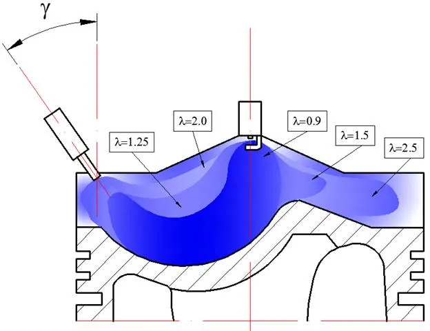
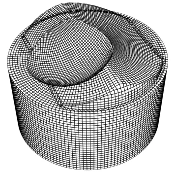
Using the CAD program a mode of charge stratification of ultra – lean combustion was elaborated based on considering the shape of the concave bowl of the piston and injection castor angle presented in Fig.1.
The small spheric bowl in the piston shown in Fig.1 works as a chamber and is located on the side of the inlet channel. The geometry of the bowl in the piston bottom is designed in such a way that the fuel sprayed from the injector falling on the concavity is directed under the ignition plug. High pressure of the injected fuel is thought to prevent formation of a fuel film on the piston bottom during refraction and supply of an adequate rich dose of fuel under the ignition plug.
An adequate gap between the injector and the ignition plug is necessary to accelerate the evaporation and diffusion of the sprayed fuel in order to make the too rich mixtures leaner around the ignition plug (λ < 0.5) which may delay the ignition. In accordance with it, the beginning initiation of injection should occur earlier and earlier with the increase in the rotational speed.
As a result, the point the fuel impinges the concavity in the piston differs at different velocities.
The geometry of the concavity and the angle of injection were designed so that the behaviour of the fuel after injection would not be sensitive to the moment and place of injection.
THERMODYNAMICS METHOD OF COMPARATIVE CYCLE ON THE BASIS OF HEAT AMOUNT INTRODUCED INTO THE CYCLE
The following assumptions were adopted for calculations:
1. Semi prefect gas is the thermodynamic factor performing the work in the cycle.
2. The amount of the factor participating in the cycle is constant; which means that losses of the mass of the factor due to leakage of the cylinder equals zero.
3. Processes of compression and expansion are polytropic.
4. For a spark ignition engine heat is supplied at a constant volume, however, the possibility of incomplete and non – total combustion is taken into account.
5. The rest of exhaust gasses (mass, temperature and pressure) left from the former work cycle are considered.
6. Heat exchanged between the factor and walls of the combustion is neglected.
7. For calculations purposes a substitutive calculation coefficient of air excess was adopted corresponding to the charge stratification in such a way that combustion of a stratified charge gives maximal pressure and temperature of combustion which is equal to the pressure and temperature of a homogeneous charge combustion.
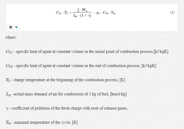
Basic equation of heat balance used for calculations takes this form:
METHOD OF COMPARATIVE CYCLE CALCULATION ON THE BASIS OF COMBUSTION PROCESS DETERMINED BY VIBE’S FUNCTION
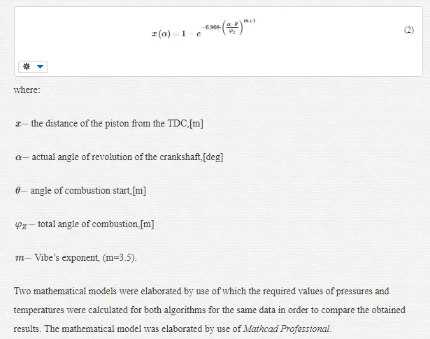
Analysis of pressures and temperatures was carried out using the known Vibe’s function determining participation of burnt fuel in the cylinder.
Vibe’s combustion function:
COMPARISON OF PRESSURE AND TEMPERATURE CALCULATED BY USE OF THE THERMODYNAMICS AND VIBE’S METHOD WITH REFERENCE TO REAL INDICATED PRESSURE IN A GDI
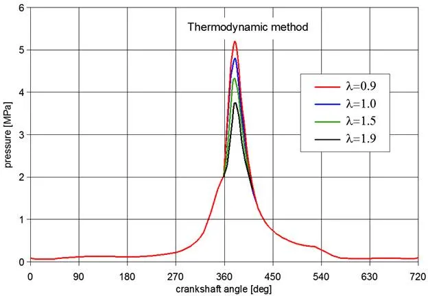
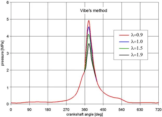
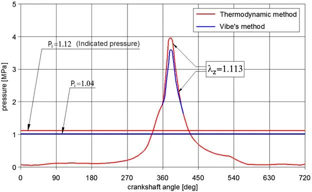
For either of these models calculation of pressures for charges of different coefficient of air excess λ were performed in order to calculate a substitute coefficient of air excess λz; these are presented in Fig.2and Fig.3 respectively. Subsequently, in Fig.4 pressure traces for the two methods were presented respectively; moreover a comparison of indicated pressures calculated by use of the thermodynamic method and Vibe’s method was given with reference to the indicated pressure in a Gasoline Direct .
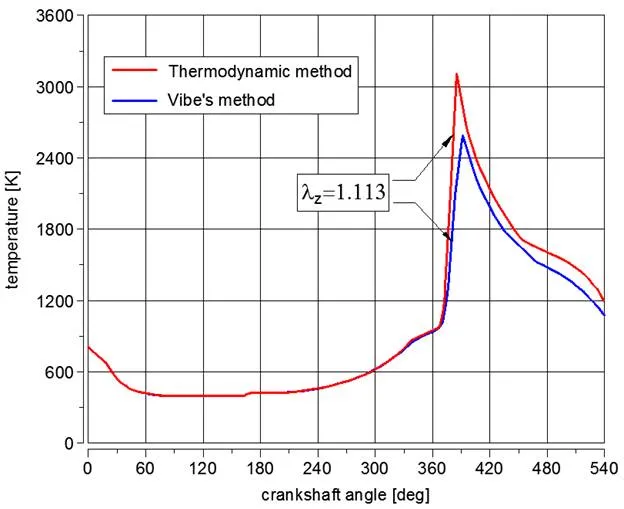
A comparison of traces of temperature changes for these methods was given in Fig.5.
For determination of the decrease in fuel consumption a comparison of maximal values of combustion pressures of a homogeneous and stratified charge was made.
Stratification of the charge was chosen in such a way that 5 zones of different coefficients of air excess λ occurred, this was shown in Fig. 1.
At the assumption of equal volumes of charges of λ = 0.9 and λ = 1.9 a subsidiary calculation coefficient of air excess λz = 1.113. Combustion of such a stratified charge gives maximal combustion pressure and temperature equal to the pressure and temperature of a homogeneous charge of λ = 1.
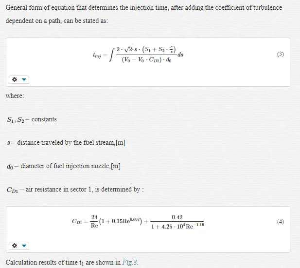
Calculation of periods of phases of fuel injection in the spark – Ignition engine with direct fuel injection during work on the heterogeneous mixture
Carried out calculations aim at determination of durations of particular phases of injected fuel stream in the Mitsubishi GDI engine during work on the stratified mixture, including resistances prevalent inside the cylinder [8]. The mathematical model was elaborated by use of Mathcad Professional.
The phases of injected fuel stream during work on the stratified charge are shown in Fig.6.
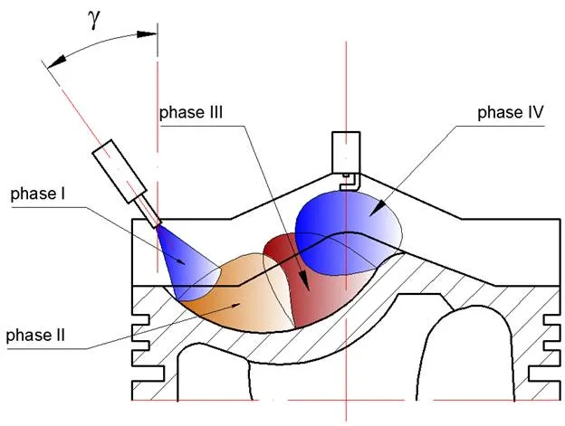
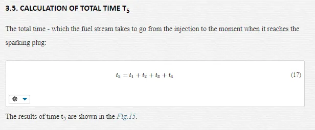
For the calculation model, the total time needed to cross a distance from injection moment to the sparking plug points reaching was divided into four stages, namely:
1. Period t1 – from the fuel injection moment to contact of the stream with the piston head, including air resistance
2. Period t2 – from the moment of entry into curvature of the piston head to the half-length of the curvature, including frictional resistance between the fuel stream and the piston head
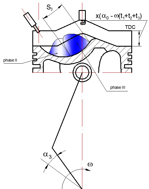
3. Period t3 – from the half-length of the piston head curvature to the moment when the fuel stream exits the head, including both frictional and air resistances for the evaporating fuel
4. Period t4 – from exit the curvature of the piston head to the moment when the fuel stream reaches the sparking plug points.
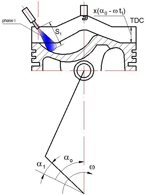
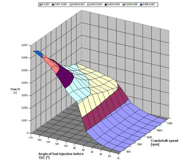
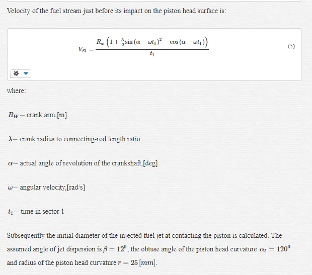
CALCULATION OF PERIOD T1
Time t1, from the fuel injection moment to contact of the stream with the piston head, including air resistance (Fig.7).
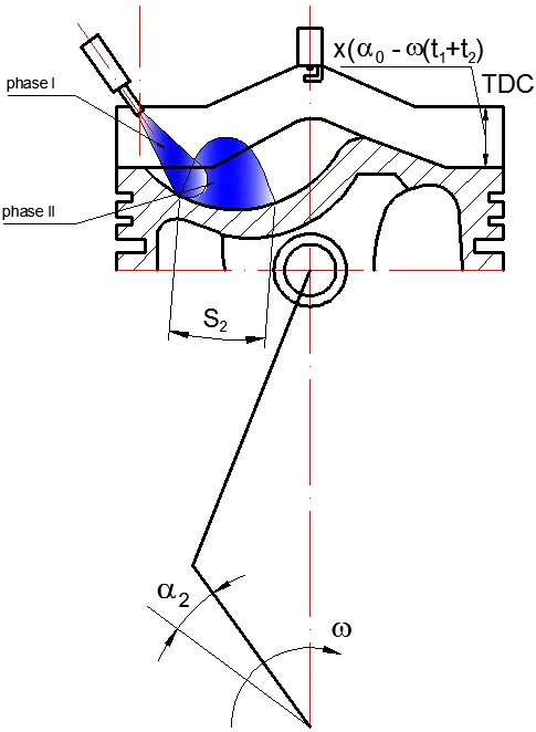
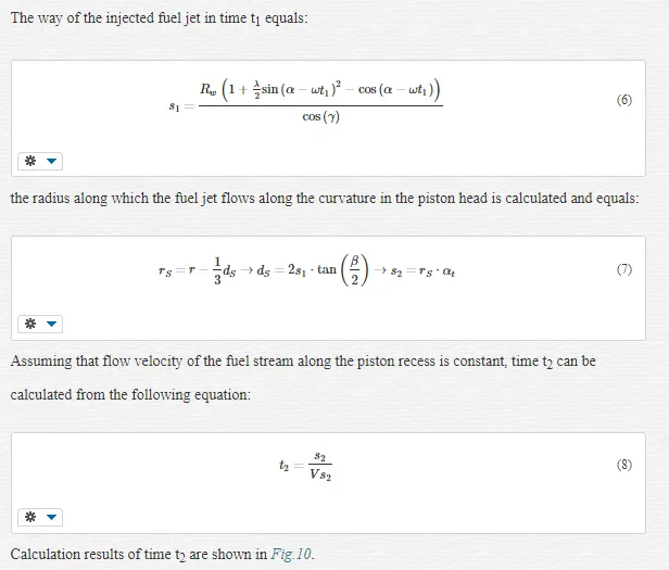
CALCULATION OF PERIOD T2
Time t2 , from the moment of entry into curvature of the piston head to the half-length of the curvature, including frictional resistance between the fuel stream and the piston head (Fig.9).
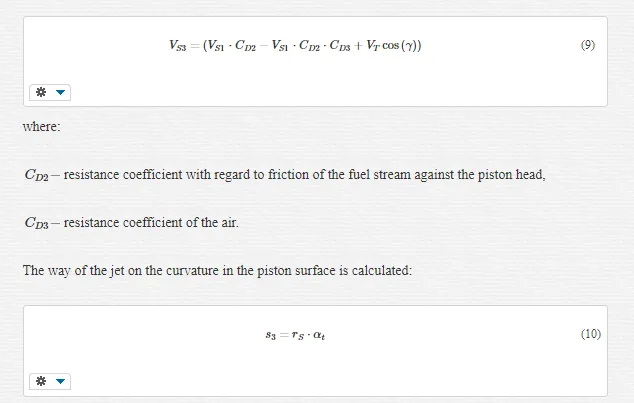
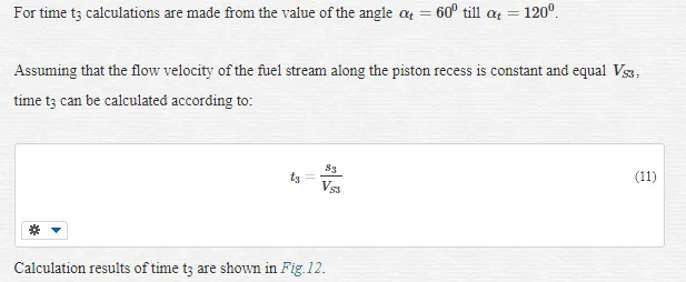
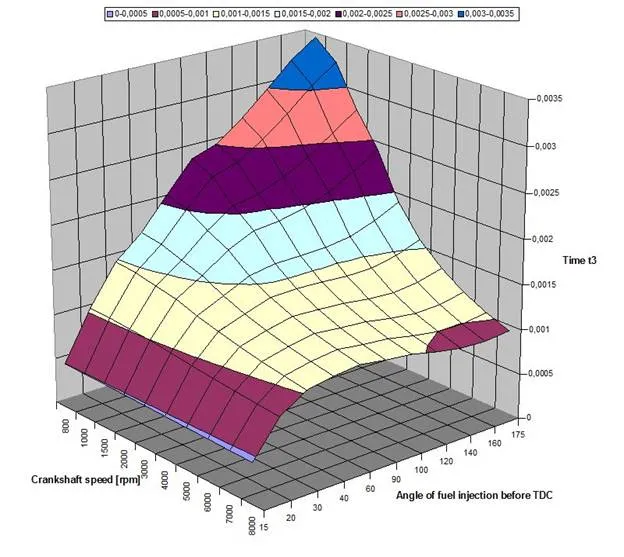
CALCULATION OF PERIOD T3
Time t3, from the half-length of the piston head curvature to the moment when the fuel stream exits the head, including both frictional and air resistances for the evaporating fuel (Fig.11).
Velocity of the fuel stream in the piston head with regard to resistance of the piston head surface and the air is:
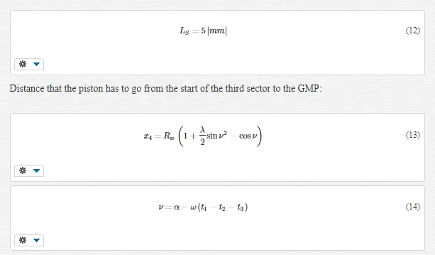
CALCULATION OF PERIOD T4
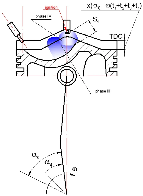
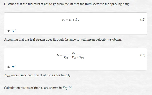
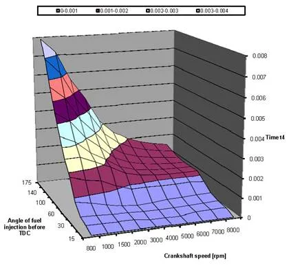
Time t4, from exit the curvature of the piston head to the moment when the fuel stream reaches the sparking plug points (Fig.13).
It is assumed that sparking plug is situated centrally in the cylinder axis, in the top of the combustion chamber. Furthermore, a distance between the piston top and the head LS is:
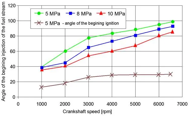
 From the calculated values of the angle by which the crankshaft revolts during the jet travel the value of the advance angle of injection with consideration of the advance angle of ignition is calculated.
It has to be emphasized that the actual injection angle has to be increased by the ignition advance angle what is superposed and presented in Fig. 16.
Modelling of injection process in gasoline direct injection engine by kiva 3v
In up-to-date combustion engines the fuel is injected directly into the cylinder, where the load has a raised temperature. The evaporation is better than at the injection into the inflow duct. With regard to a very short time lapse between the start of injection and the ignition during the mixture stratification in recent gasoline engines with direct fuel injection into the cylinder the presentation of a precise mathematical model describing evaporation of fuel drops is necessary.
During fuel injection disintegration of drops, falling into smaller and smaller ones, takes place. They are subjected to aerodynamic forces which are the direct cause of their disintegration. The presentation of a precise mathematical model of the process of drop movement, disintegration, and evaporation is, so far, not possible. However, a number of models based upon aero- and thermodynamic laws and experimental investigations have already been built. As a rule, reciprocal collision of drops is not considered. In some models only one kind of drop contact with the wall (rebouncing or spilling) is assumed. The best known, at present, models of fuel evaporation are the models given by Spalding [6] and included in the module GENTRA in the programme Phoenics of the firm CHAM and programmeKIVA.
Mathematical models considered in these programmes are more suitable for numerical simulation of the fuel injection process in gasoline engines. Apart from it, the mathematical model given by Hiroyasu [4] and the PICALO model should also be considered.
In program KIVA 3V make use of complicated mathematical models describing the behaviour of the fuel injected into the engine cylinder, and so: shaping of the fluid jet (Reitz model [5]), fuel drops breakup (TAB – Taylor Analogy of Breakup procedure [3]), evaporation of fuel drops (Spalding model [6]), resistance and movement forces (Amsden model [2]), turbulence of the charge in the combustion chamber (two – equation κ- ε model [8]).
GEOMETRY OF THE CALCULATION MODEL
The program for computer modelling and simulation of combustion engine KIVA 3V possesses a large, developed, graphic interface which may additionally consider the inflow and outflow system and create complicated curved surfaces describing, as in our case, the head of piston. For such a complicated system as the combustion chamber Mitsubishi GDI the commercial program KIVA 3V in the Laboratory Los Alamos describes fully the physical and thermodynamical processes inside the cylinder. In Fig.17shows a geometrical model of a piston of a gasoline engine type 4G93GDI of the firm Mitsubishi.
In the case of an irregular combustion chamber calculation of the size of the contact surface of flame and cylinder walls and head can be performed applying division of the w hole surface above the piston into a number of elementary volumes. This method should be applied at irregular shapes of the combustion chamber.
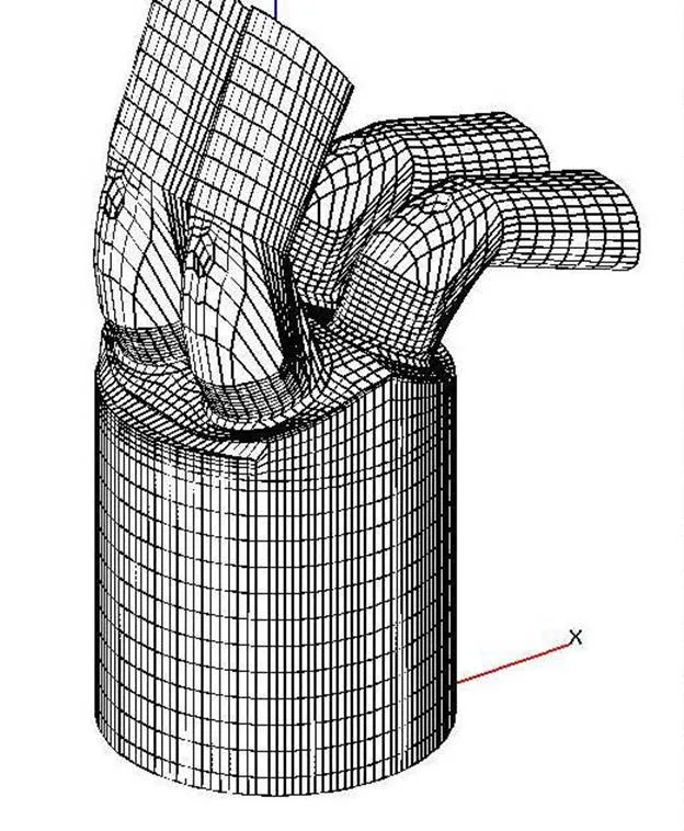
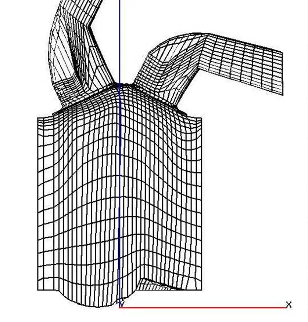
Cylinder was divided into 20 400 cells (30x34x20) and each 4 pipes into 1900 cells. Total number of cells of whole system when piston is in BDC amounted 29680 cells. The grid consists of a cylinder 17 of horizontal layers. 13 layers of equal thickness falls to 80% of piston stroke starting from the bottom dead centre. The remaining 4 layers around the top dead centre was concentrated to obtain more advantageous terms of the simulation of combustion process that takes place there (combustion chamber). Mesh of one cylinder with two inlet and two exhaust pipes and pent-roof combustion chamber is shown in Fig.18. In order to determine of engine thermodynamic parameters it required a special division of cylinder layers along the wall and more complex grid inside of combustion chamber. Cross section of the cylinder along symmetric axis (Fig.19) shows also a bowl in the piston and layers adopted both to the pent-roof chamber and piston head. Piston head was created by CAD system and transformed to pre-processor file. For this reason a special algorithm of interpolation was written to adopt in Lagrange coordinates. Mesh of the cylinder changes during piston moving and movement of valves also takes effect on creation of mesh in every time step. Mesh of combustion chamber at 27 deg after TDC when inlet valves are opened is shown in Fig.20.

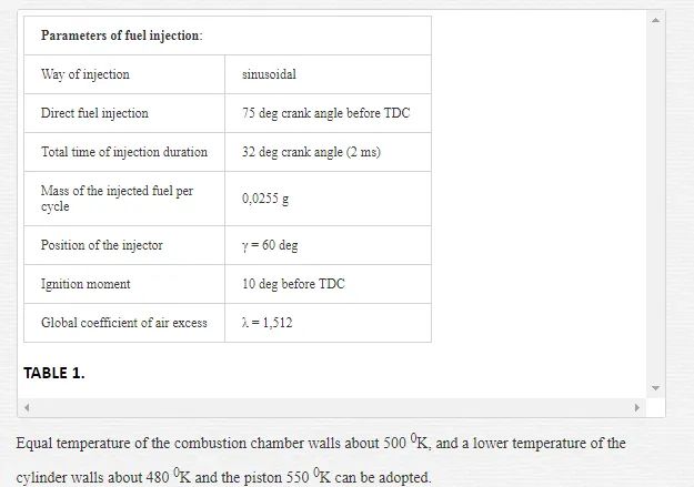
PARAMETERS OF THE CALCULATION MODEL
During compression stroke fuel of high pressure is delivered by injector located between two intake pipes. Fuel is injected towards the piston bowl and is turned by its wall to the spark plug. However injection time should be strictly defined in dependence of engine speed and ignition angle[3]. Parameters of fuel injection are shown in Table 1.
ANALYSIS OF PARTICIPATION OF THE GASEOUS PHASE
In the enclosed illustration (Fig.21–22) changes participation of the gaseous phase inside the cylinder of the gasoline direct injection engine from the moment of injection till the moment of ignition.
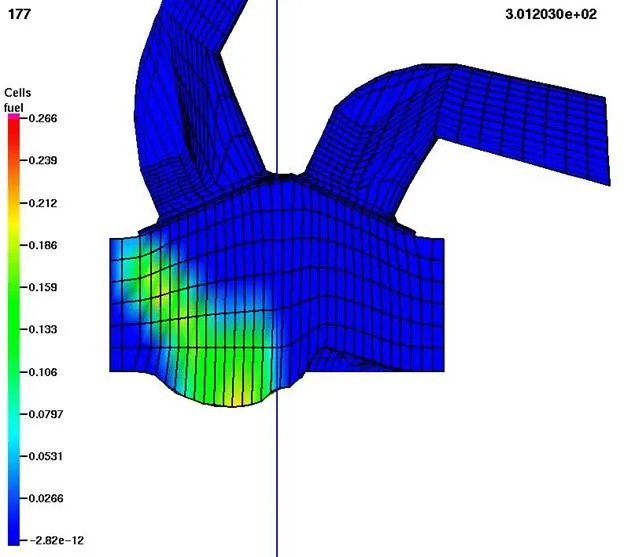
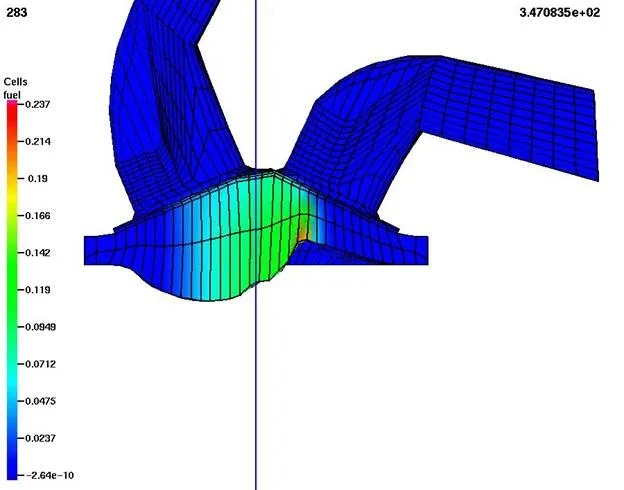
We can see a turning of fuel jet to the spark plug, but concentration of fuel is observed on piston bowl. Near TDC some of liquid fuel flows to the squish region and sometimes cannot be burned. During motion of jet fuel vaporize and on its boundary is more vapours than inside of jet. Because of restricted volume of this paper it cannot be presented distribution of equivalence fuel-air ratio. However near spark plug air excess coefficient is enough to begin of combustion process. Ignition of spark plug took place 10 deg before TDC.
ANALYSIS OF TEMPERATURE DISTRIBUTION IN THE CYLINDER GDI ENGINE
In the enclosed illustration (Fig.23–24) changes of temperature inside the cylinder the GDI engine from the moment of injection till the end of the combustion process are shown.
During injection process there is observed decrease of temperature of charge where is liquid fuel and is caused by vaporization process. When piston is near TDC temperature of charge in a squish region is higher than in the centre of combustion chamber. The process of combustion during stratified charge mode is irregular, as a result of conductivity of fuel and gas, first of all ignite the regions with fuel vapour surrounding liquid fuel. It can be observed also during visualization process. The distribution of temperature shows the whole process of combustion and it proceeds in another way than in conventional engine with homogeneous charge. Just at the end of this process the charge in the middle of combustion chamber burns as a result of higher temperature and vaporization of fuel jet.


Test bed investigation
Test bed investigations were divided into two basis stages:
1. The first stage includes elaboration of the visualization process of fuel injection and combustion of stratified charges for various loads and chosen rotational speeds of engine.
By use of a VideoScope 513 D of the firm AVL the movement of fuel jet will be followed from the moment of injection, fuel rebouncing from the piston head, up to the moment of its entering under the ignition plug, and subsequently spreading of the flame from the moment of ignition until the end of the combustion process [7].
1. The second stage includes carrying out of test bed investigations aiming at determination of increase in total efficiency of a Gasoline Direct Injection Engine.
VISUALIZATION OF INJECTION COMBUSTION PROCESS DURING ENGINE WORK ON STRATIFIED MIXTURE
The carried out visualization concerned the process of injection and combustion during engine work on stratified mixture [10]. The recording was carried out for rotational speed of the engine 2400 [rpm] for partial load. The value of specific fuel consumption was 238 [g/kWh]. The fuel injection took place for 780 CA before TDC.
Below, in the presented film frames (Fig.25–26) chosen photographs concerning fuel injection into the cylinder of GDI engine.

 In Fig.27–28 are shown chosen film frames from the visualization concerning the combustion way in the GDI engine during engine work on stratified mixture. The moment of ignition took place for 10 deg CA before TDC.


TEST BED INVESTIGATIONS OF THE ENGINE 4G93GDI
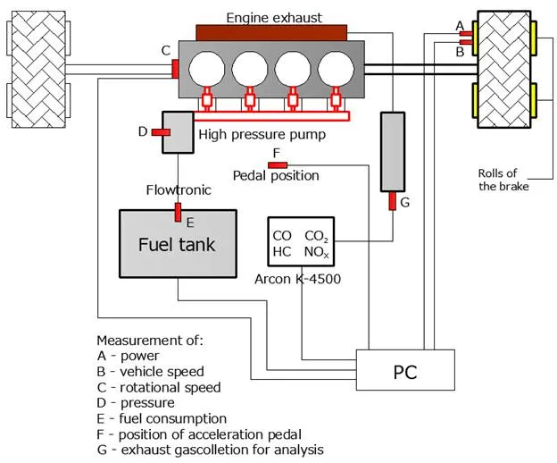
A roller chassis test bed equipped with a water, electrically controlled brake, whose maximal moment is 180 [Nm] was adopted for a test bed for determination of speed and load characteristics of a Mitsubishi GDI engine of 1834 cm3 capacity.
The system was equipped with a vehicle speed meter V [km/h] and power on wheels [kW].
The system for fuel consumption measurement was equipped with apparatus of the type Flowtronic, measuring fuel consumption per hour Ge [l/h], connected to the fuel pump located in the fuel tank.
The system for measurement toxic component content in exhaust gases of the Arcon Olivier K-4500 was connected by use of a sound to the exhaust system. The measurements considered content of CO, CO2, O2, HC and the measurement of the coefficient of air excess λ.
The system for measurement of rotational speed of the engine was equipped with an encoder of the crank angle of the firm AVL type Angle Encoder 364 on a pulley.
Additionally a positioner permitting exact determination of the position of the accelerator.
All measurement systems were integrated with the central measurement computer mounted on the test bed for precise determination of all possible data for a given rotational speed and load of the investigated engine.
The scheme of the measurement test bed for determination of speed and load characteristics of the investigated engine was given in Fig.29.
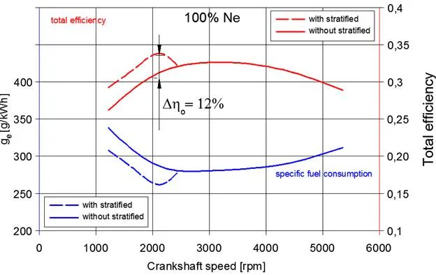
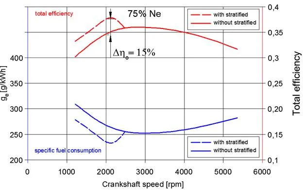
For determination of total efficiency of the engine Mitsubishi GDI of 1834 cm3 capacity with direct fuel injection use was made of the elaborated characteristics of speed obtained during test bed investigations the relation of specific fuel consumptions in function of rotational speed of the engine.
With regard to considerable decrease in fuel consumption per hour and per unit within the rotational speed from 750 – 2700 [rpm] caused by engine work in the mode of stratified fuel-air mixture (λ ≅ 1,5-2,1 in dependence on engine rotational speed an load) the diagrams were to be complemented by additional characteristics of specific fuel consumption. With this aim in mind diagrams of specific fuel consumption in the same range of rotational speed 750 – 2700 [obr/min] were drawn in such a way as for an engine working on homogeneous mixture ((λ≅1). In consequence of it the value of specific fuel consumption does not show the characteristic jump from one mode of work to the other.
Fig.30-31 show traces of changes of specific fuel consumption and total efficiency of GDI engine in function of rotational speed.
Conclusions
1. The methods presented in this study, of determining the comparative cycle for this fuel supply system may be applied to the initial calculations in the designing of the gasoline engine with direct petrol injection,
2. The determination of the best parameters for the fuel injection process requires the accurate setting of the time the fuel spout requires to travel the distance from the injector exit to the spark plug electrodes.
3. The results obtained during the visualization of the process of injection and combustion of the luminar loads display the actual conditions occurring inside the engine cylinder and they become essential in the accurate determination of the parameters deciding about the correct course of the gasodynamic phenomena.
4. A considerable increase in the total efficiency of the gasoline engine is observed during the combustion of lean fuel-air mixtures, due to lower temperatures during the load creation process, which allows applying larger values of the compression ratio to 14, which directly translates to the increase of the total efficiency.
5. The results of computer calculations and stand research included in this work constitute a comprehensive complement of the knowledge about the creation and combustion of laminar loads in the gasoline engines with spark ignition with direct petrol injection.
6. The increase in the total efficiency of GDI engine determined on the basis of test bed investigations varies within the limits Δη0 = 10 ÷ 17% in dependence on the rotational speed and load of the engine.
7. Applying the direct fuel injection of lean mixture combustion strategy definitely improves the working parameters of the internal combustion engine and constitutes the basis for further developmental work on this area.


Comments are closed