An Intelligent Transportation System (ITS) is a system based on wireless communications which has been investigated for many years in order to provide new technologies able to improve safety and efficiency of road transportation with integrated vehicle and road systems. It combines all aspects of technology and systems design concepts in order to develop and improve transportation system of all kinds. ITS, which utilise information and communications technology in vehicle as well as within the roadside infrastructure, can also be used to improve mobility while increasing transport safety, reducing traffic congestion, maximising comfort, and reducing environmental impact (Andrisano et al., 2000). Intelligent transportation systems and applications can improve the quality of travel by selecting routes with up-to-the-minute information data, giving priority to response vehicle teams, notifying drivers about road incidents, and delivering ITS services to drivers. They can reduce fuel consumption by routing the vehicles to their destinations so that fuel waste is significantly reduced, and also fully utilise the capacity of the existing road vehicular networks by controlling the flow of vehicles based on traffic monitoring and detecting congestions.
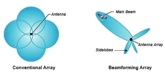
Vehicles within the ITS framework have to work in an autonomous manner to sense the driving environment and in a cooperative manner to exchange information data such as braking and acceleration between vehicles and also traffic, road, and weather conditions between vehicles and roadside units (Han & Wu, 2011). Hence, radio communications links between vehicles on a motorway are envisaged, leading to the formation of ad-hoc networks between clusters of vehicles and roadside beacons. System performance and analysis can be improved in various ways by the use of smart antenna systems and techniques. These microwave systems fulfil the requirements of improving coverage range, capacity, data-rate, and quality of service (QoS). Smart antenna systems are generally classified as either switched-beam antenna systems or adaptive arrays. Switched-beam antenna systems use fixed multiple beamforming networks (BFNs) in order to create various beam patterns based on the different microwave beamforming techniques and technologies. These smart systems can be used to increase the wireless channel capacity limited by the presence of interference. By using narrow beams available from these systems, it is possible to increase the gain in the desired signal direction and to reduce it toward interference directions. They can also be used for mobile communication base stations in order to provide space-division multiple access (SDMA) capabilities. On the other hand, growing demand in intelligent transportation systems means there is a need for multiple antennas with multiple beams.
Switched-beam antenna systems can greatly improve the performance of the intelligent transportation systems by providing better link quality and high immunity to interference.
Also, generating multiple beams using an array along with having wide bandwidth and beam steering capability are of crucial importance for modern wireless communication systems. For this purpose, various multiple beamforming networks are introduced to have control over the amplitude and phase at each element of the antenna array. Microwave passive networks form an important class of these networks and they have been widely used in switched-beam antenna systems. Two well-known examples of such networks are the Rotman Lens (lens-based beamforming network) and the Butler Matrix (circuit-based beamforming network). They increase the system capacity and provide higher signal-to- interference ratio, consequently enhancing the overall automotive telematics performance.
This chapter presents the novel designs of steerable microwave beamforming networks employing an 8×8 Rotman Lens for operation at 6.3 GHz (C-band), and cascaded 4×4 Butler Matrices for operation at 3.15 GHz (S-band). The microwave beamforming networks are intended for intelligent transportation systems and applications. Although the frequency range likely to be allocated to such systems is 63 GHz, where the short transmission range allows multiple frequency re-use, the microwave networks are frequency scaled models to verify the concept. The objective of this investigation is to develop microwave beamforming networks suitable for a use in vehicle-to-vehicle (V2V) and vehicle-to-infrastructure (V2I) communications. The microwave beamforming networks demonstrate appropriateness to develop well-established designs for systems that can be utilised in ITS applications and framework and vehicular ad-hoc network (VANET) telematics which is the convergence of telecommunications and information processing with application of vehicle tracking.
Smart antennas and microwave beamforming techniques
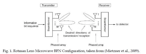
In addition to higher bit-rates and smaller error-rates, microwave beamforming techniques can also be utilised in order to improve the signal-to-noise ratio (SNR) at the receiver and to suppress co-channel interference (CCI) in a multi-user vehicular scenario, thus improving the SINR at the receiver. Using microwave beamforming techniques, the beam patterns of the antenna array can be steered in certain desired directions, whereas undesired directions can be suppressed. Consider an antenna array with N antenna elements, which receives an RF signal from a certain direction. Due to the geometry of the antenna array, the impinging RF signal reaches the individual antenna elements at different time instants, which causes phase shifts between the different received signals. If the direction of the impinging RF signal is known, the phase differences of the RF signals can be compensated by means of phase shifters or delay elements, before the received signals are added up. As a result, the overall antenna pattern of the phase array will exhibit a maximum in the direction of the impinging signal. This principle is called microwave beamforming and is shown in Fig. 1, which is equivalent to a mechanical rotation of the array. In a vehicular communication scenario, transmitted RF signals often propagate via a line-of-sight (LOS) path between transmitter and receiver and via paths that are associated with significant reflectors and diffractors in the environment (such as large trucks). If the directions of these dominant propagation paths are known at the receiver side, microwave beamforming can be applied in order to adjust the receiver beam pattern such that it has a high directivity towards the dominant angles of reception to accomplish significant antenna gains. Due to the required
equipment and processing power, however, the use of smart antennas is currently limited to stations that are fixed on vehicles (Mietzner et al., 2009).
Smart antennas are also beneficial in multi-user vehicular scenarios, in order to suppress CCI. Again, both transmitter- and receiver-sided microwave beamforming can be employed for mitigating CCI. When transmitting, each user can adjust the beam pattern such that there are nulls in the directions of other co-channel users and a high directivity towards the desired direction of radiowave transmission. Hence, the SINR for the other co-channel users is improved as well as the SNR at the desired receiver. Similarly, when receiving each user can adjust the beam pattern such that directions of other co-channel interferers are nulled and desired directions of reception are enhanced and therefore each user can improve the received SINR. The use of smart antenna systems for CCI cancellation offers the opportunity to accommodate multiple co-channel users within the same frequency band. This concept is referred to as SDMA (Mietzner et al., 2009).
A multiple microwave beamforming network is one with a capability to form many beams in different directions from the same aperture. If a separate RF transmit or receive system is connected to each beam port, simultaneous independent operation in many directions can be obtained. Alternatively, a single transmit or receive system can be connected to the beam ports through a multiple-way RF switch giving a sequentially scanning antenna.
Switched-beam smart antenna systems may be cheaper than an equivalent phased array, particularly when few beam signals are needed. The creation of a multiple beam antenna using a multiple microwave beamforming network has the advantage that no devices for frequency changing are necessary. The technique therefore has the potential to be simpler and lower in cost than IF, digital, and optical frequency methods. Indeed many antenna configurations, such as lenses, have inherent multiple beam capabilities. In these cases it is only necessary to replace the single feed by an array so that each array element forms one of the multiple beams. The field of microwave beamforming networks encompasses two main research areas namely lens-based quasi-optic types, involving a hybrid arrangement of either a lens objective with a feed array, and circuit-based types used to feed antenna arrays. Circuit-based microwave beamforming networks use transmission lines, connecting power splitters, and hybrid couplers in order to form multiple beam networks. The phase shifts required to produce multi-beam scanning are provided by lengths of transmission line. Lens-based microwave beamforming networks will produce high-gain beams over narrow scan ranges with lenses giving better beam control due to their increased design degrees of
freedom. Circuit-based networks (Butler Matrix) have the travelling wave or corporate feed characteristics and can be used in limited size arrays as can the Rotman Lens, which in addition will give wide bandwidth (Hall & Vetterlein, 1990).
Rotman lens microwave BFN analysis and design
The Rotman Lens is an attractive passive microwave lens-based beamforming network due to its low cost, reliability, design simplicity, and wide-angle scanning capabilities. It is a device that uses the free-space wavelength of a signal injected into a geometrically configured waveguide to passively shift the phase of inputs into a linear antenna array in order to scan a beam in any desired signal pattern. It has a carefully chosen shape and appropriate length transmission lines in order to produce a wave-front across the output that is phased by the time-delay in the signal transmission.
A Rotman Lens achieves beam scanning using equivalent time-delays that are created by the different path lengths to the radiating elements. These lengths depend on the relative position between the beam port and the array ports on the structure. As long as the path lengths exhibit constant time-delay behaviour over the bandwidth, the lens is insensitive to the beam squint problems exhibited by constant phase beamformers (Weiss, 2010). Each input port will produce a distinct beam that is shifted in angle at the system output. The design of the lens is controlled by a series of equations that set the focal points and array positions. The inputs, during the design of the system, include the desired number of beams and array elements, and the spacing of the elements (Penney, 2008). Since Rotman Lens is a true-time-delay (TTD) device, it produces beam steering independent of frequency and is therefore capable of wide-band operation. Also, the cost of a Rotman Lens implemented on microwave material primarily driven by the cost of the material itself and the price of photo etching (Weiss et al., 2007).
Rotman lens microwave BFN contour synthesis
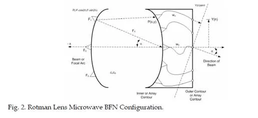
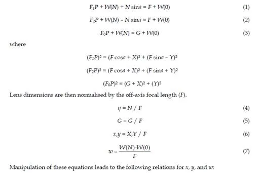
The synthesis of the microwave lens assumes several input parameters which are used to compute the inner contour (array contour) point as well as the line lengths. These parameters are element spacing (η), focal ratio (g), lens width (G or F0), and scan angle (α) (Fig. 2). The lens inner contour points and transmission line lengths are solved for using the technique of path length comparison (Rotman & Turner, 1963).

Rotman lens microwave BFN performance and phase error analysis
In order to calculate performance of the microwave lens, the coupling between ports is approximated using aperture theory and a uniform distribution to the port aperture is implied. These port radiation patterns are used to compute the direct path and reflected path propagation from port to port. Also, to improve the response of the outer beams, the beam and array ports are adjusted so that each line is pointing toward the centre of the lens on the opposite side rather than being normal to the microwave lens surface (Maybell, 1981).
Phase error is calculated by comparing electrical lengths along two distinct paths from a given beam port through the microwave lens (Fig. 3). The first path travels through any one of the off-axis array ports, through its taper and transmission line, and finally along the path from the array element phase centre to the beam phase front. The second path begins at the same beam port but travels through the centre of the array curve and through a length of line common to all array ports. The comparison of these electrical lengths obtains the phase error for this beam port. This is done over the list of beam ports to produce a phase error.
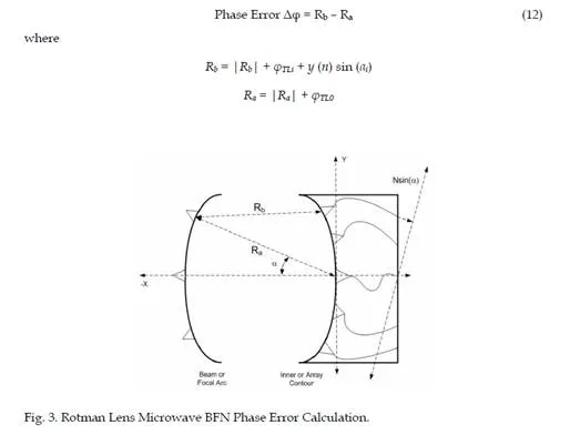
When a feed point is placed at any one of the focal points, the corresponding wave-front has no phase error. When the feed is displaced from these lens focal points, the corresponding wave-front will have a phase error. However, for wide-angle microwave beam scanning, the lens must be focused at all intermediate points along the focal arc.
8×8 ITS Rotman lens microwave BFN design and performance
As Fig. 4 indicates, a realistic 8×8 ITS Rotman Lens microwave beamforming network is designed and simulated for a use in intelligent transportation systems and applications. The design parameters are based on those used in previous section. In this case, the microwave lens is designed to have 8 beam ports, 8 array ports suitable for an 8-element antenna array, a beam scan angle of ±50° at a centre frequency of 6.3 GHz, and an element spacing of 28 mm. The prototype for the lens is fabricated as a microstrip with a 50 Ω impedance transmission lines on Taconic TLC-30 substrate with the dielectric constant (εr) of 3.0, substrate thickness (H) of 1.3 mm, and loss tangent of 0.003. The design gives the microwave lens a compact size of 35.91 cm × 25.80 cm. The array ports have also been spaced in such a way that elements of the antenna array can be directly attached to the microwave network. Design, synthesis, and analysis of the 8×8 microwave Rotman Lens and its variants are based on real-time analysis of geometrical optics (GO).
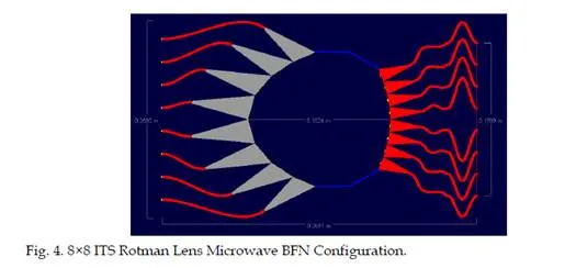
The above microwave lens has an elliptical curvature on the beam port side. In this design, dummy ports are replaced with the terminated absorber sidewalls in order to introduce a novelty in the microwave lens structure, reduce the network size and unwanted reflections (and therefore reduce phase errors at the array ports), and increase the performance of the lens. The geometry of the transmission line routing is adjusted in a way to ensure no overlapping, proper spacing between lines, proper curvature, and maintaining overall lens physical length requirement. To obtain the desired performance, the lens requires to be tuned in terms of phase error or the array factor. The tuning involves adjusting the focal ratio (g) of the lens that will minimise the error reported by the phase error. This factor determines the curvature and focus of the lens, and if not adjusted accurately, will produce a messy beam. Hence, the focal ratio (g) is adjusted to 1.2670 in order to minimise the beam to array phase error and to produce well-focused beams (Fig. 5).
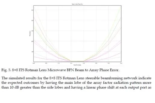
a function of frequency. The beam to array coupling amplitude (the array ports distribution from a given beam or set of beams) for the array ports 9 to 16 has expected outcome of –9 dB to –13 dB has been obtained as a result of the accurate lens design and it confirms how the amplitude distribution along the array contour is much more uniform with beam port pointing enabled. Also, the progressive phase shift for the lens array ports exciting beam port 5 ensures the generation of eight distinct beams and beam scanning capabilities. It is computed using the linear distance between the ports in the dielectric medium chosen.
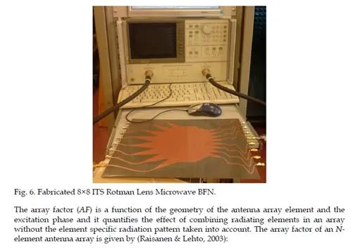
The fabrication of microwave network was carried out and the lens was then extensively measured on a network analyser over a frequency range of 5.5 GHz to 7.5 GHz with the frequency of operation as 6.3 GHz. Fig. 6 indicates the fabricated microwave network being tested. Only one beam port and one array port (S21) are measured at a time and all other ports are perfectly terminated using 50 Ω termination loads.
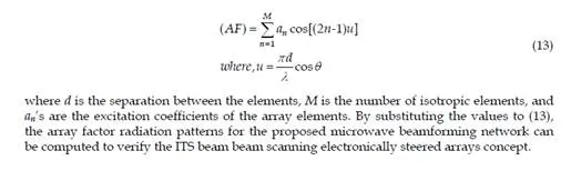
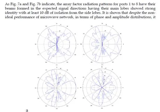
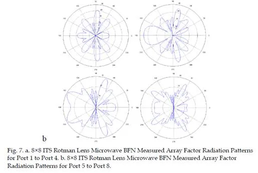
is still capable of forming well-defined beams suitable for the beam steering experiments by causing the main lobe to be directed in certain directions for ports 1 to 8.
The difference in signal beam shape between the measured radiation patterns and simulated array factors is mainly in the nulls between the beams, which are not deep enough as the measured results because of small phase and amplitude deviations, the cross-coupling effects that are not taken into account in simulations, non-uniformity of transmission line width, and errors occurred during fabrication, measurement, and soldering. By eliminating the mentioned errors and using a shielded metal box with absorbing foams attached to the inner lid to reduce the interferences, the overall system performance will be improved and enhanced in terms of achieving high-gain narrow-beams with desired directions, and the relative phase shift will have a uniform distribution.
The proposed system can be used as the radio zone control technology units which scans the radio zone (antenna beam) in accordance with the average speed of a vehicle group in order to decrease the number of handovers within the specified continuous area. The microwave lens can also be integrated with amplifiers between the lens and the radiating elements as well as an RF switch array for selection of the signal beam ports and an A/D converter which samples the received signal and converts it to a digital signal and a DSP processor unit which then performs a Fast Fourier Transform (FFT) of the digital signal, and the amplitude and the phase parts are separated out.
ITS applications have generally been classified into three main categories with respect to their functionalities as safety, efficiency, and comfort applications. Safety applications minimise the risk of accidents and reduce the severity of the accident if it still occurs (collision avoidance, road sign notifications, incident management). Efficiency applications increase traffic efficiency by managing the traffic flow, and monitoring vehicles and road conditions. The purpose of comfort applications is to provide entertainment facilities and information to passengers by means of Internet access technologies (Dar et al., 2010).
Integration of digital signal processing unit with microwave beamforming network based on the 8×8 Rotman Lens will form a hybrid microwave-digital distributed beamforming network that can be employed in vehicular phased arrays and collision avoidance radar systems in order to support the ITS safety applications. Also, the proposed microwave network system can further be extended to wide-band structures to support the frequency of operation of 63 GHz for vehicle communication systems.
Butler matrix microwave BFN analysis and design
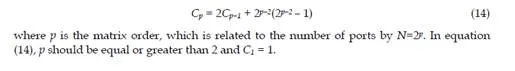
The Butler Matrix which is recently used due to its easy fabrication process and low cost, is a method of feeding an antenna array. It requires N beam (input) ports, N output ports, (N/2) log2(N) hybrid couplers, and (N/2) log2(N–1) fixed phase shifters to form the N×N network for an N-element array (Ahmad & Seman, 2005). When a signal excites an input beam port of the matrix, it produces different inter-element phase shifts between the output ports. To calculate the number of crossovers needed (14) may be used (Corona & Lancaster, 2003):
In this ITS microwave beamforming network, four hybrid couplers, two crossovers, and two fixed phase shifters are combined to obtain the 4×4 Butler Matrix. The phase differences are
±45° and ±135° from port 1 and port 4, and port 2 and port 3, respectively. The output ports have been spaced in such a way that elements of the antenna array can be directly attached to the microwave network. If the matrix is connected to an antenna array, then the network will act so that the array will have a uniform amplitude distribution and constant phase difference between adjacent elements to generate orthogonal beams. The Butler Matrices are then cascaded in order to produce narrow-beam and broad-beam output that could provide multi-channel operation for automotive telematics applications, particularly for vehicle-to- vehicle (V2V) and vehicle-to-infrastructure (V2I) automotive communications.
The Butler Matrix microwave beamforming network is theoretically lossless in that no power is intentionally dissipated in terminations. There will always be, however, a finite insertion loss due to the inherent losses in the hybrid couplers, fixed phase shifters, and transmission lines that make up the matrix. The Butler Matrix passive beamforming antenna also requires that the individual beam patterns be orthogonal in space (Skolnik, 2000).
Independent orthogonal beams mean that when two or more beam input ports are simultaneously excited, the resulting radiation is a linear superposition of the radiations that would be obtained when the ports are excited separately. In addition, when a signal is applied to one port it should have no output at the other ports. An antenna which is lossless and passive means that the radiated power is the same as the input power. Fig. 8 shows the topology of the Butler Matrix. The phase shift at the matrix output ports can be determined by summing up all the phase shifts of signal paths. Table 1 also indicates the resulting phase shift’s characteristics at the matrix output elements. It was designed in such a way that when current excited to any input ports will only has one constant as shown in Table 1.
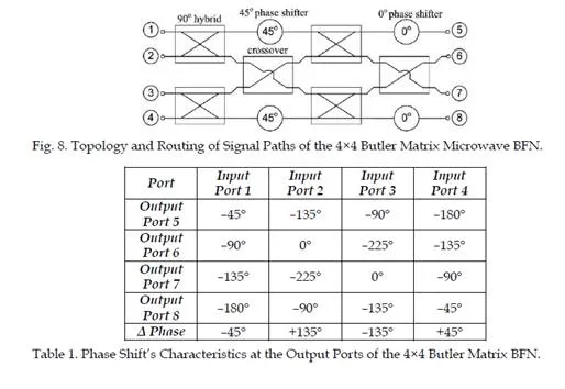
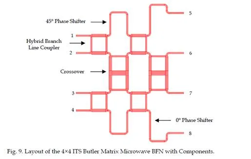
Fig. 9 shows the proposed planar configuration of the 4×4 ITS Butler Matrix microwave beamforming network obtained as a result of the accurate branch line coupler, crossover, and phase shifter components design. The input and output ports are connected through the phase shifters and branch line couplers such that when a signal is applied to any input port, the matrix produces equal amplitude signals at all the output ports. The 45 degree and 0 degree phase shifters, together with phase adjustment, are obtained by connecting a transmission line at the output port of the hybrid coupler to the input port of the other hybrid coupler. At the Butler Matrix output ports, additional transmission lines are placed in such a way that antenna array elements can be directly connected to the network. The design gives the 4×4 ITS Butler Matrix network a compact size of 11.6 cm × 9.1 cm for enhanced operation and better performance (Rahimian & Rahimian, 2010).
4×4 ITS Butler matrix microwave BFN realisation
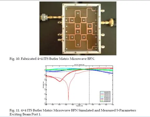
The fabrication of the 4×4 ITS Butler Matrix microwave beamforming network has been carried out and the measured results have slight error compared to simulated results. The prototype for the matrix is fabricated as a microstrip with a 50 Ω impedance transmission lines on FR4 substrate with the dielectric constant (εr) of 4.7 and thickness (H) of 0.8 mm, and loss tangent of 0.01. The ITS Butler Matrix microwave beamforming network was then extensively measured on a network analyser over a frequency range of 2.5 GHz to 3.5 GHz with the frequency of operation as 3.15 GHz. The Butler Matrix has been shielded with a metal box along with absorbing foam attached to the top lid of the inner box in order to reduce internal coupling and external interference effects. Fig. 10 indicates the fabricated ITS beamforming network being tested. Only one beam port and one output port are measured at a time and all other ports are perfectly terminated using 50 Ω termination loads.
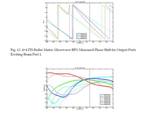
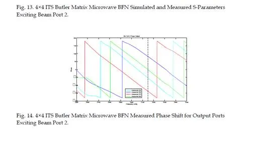
Fig. 11 and Fig. 13 indicate the simulated and measured S-parameters exciting beam port 1 and beam port 2 respectively. At an operating frequency of 3.15 GHz, the simulated results agree with the measured results. As Fig. 12 and Fig. 14 indicate, the measured progressive phase shift for the Butler Matrix microwave beamforming network output ports exciting port 1 and port 2 respectively ensure the generation of four different beams at 3.15 GHz.
By using the narrow-beam signals available from the ITS Butler Matrix, it is possible for a vehicle to increase gain in the desired signal directions and reduce the gain in interference signal directions. The differences between the simulations and measurements and slight distortion of the beam shape might be due to the employed FR4 board and fabrication process, non-uniformity of matrix transmission line width, cross-coupling effects, and measurement errors. This Butler Matrix microwave network can be used as a planar passive BFN for multi-beam antennas used in automotive telematics and ITS applications.
The microwave beamforming network was designed to be placed anywhere on the envelope of the symmetrical cut-plane running through the centre of the vehicle. Possible antenna placement positions are therefore on the roof of the vehicle or inside the front and rear bumpers with a plastic radome. Antenna location is important to permit a mounting, which has little impact on vehicle styling, be of low cost, and be capable of addition to the vehicle with minimum re-design of surrounding components.
Cascaded ITS Butler matrices microwave BFN design and performance
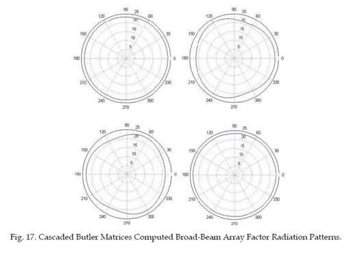
As Fig. 15 indicates, the proposed ITS Butler Matrix microwave beamforming network has been cascaded back-to-back in order to produce narrow-beams and broad-beams suitable for V2V and V2I automotive communications. Signals entering the input ports of the first Butler Matrix microwave beamforming network are subdivided into equal amplitude with progressive phase variation across the matrix output ports, for high-gain and narrow-beam reception that are potential for ITS long-range automotive communication.
These signals are then fed into the Wilkinson power dividers. The signal from one end of each Wilkinson power divider forms a narrow output beam while the signals from the other ends of the Wilkinson power divider are fed into the second Butler Matrix network in order to regenerate the broad-beam signal characteristics of the individual radiating elements. As a result, high-gain and narrow-beam signals are produced on the output of the first Butler Matrix network while broad-beams are produced on the output ports of the second Butler Matrix network that are suitable for ITS short-range automotive communication.
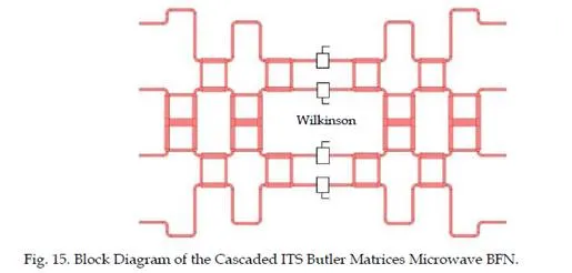
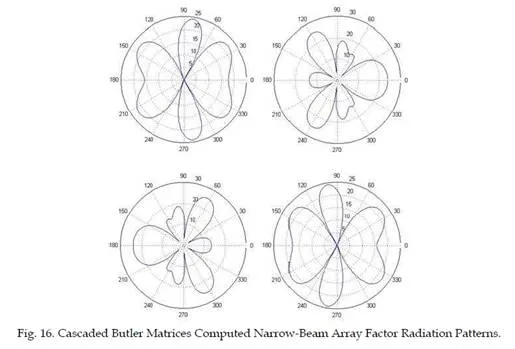
Fig. 16 and Fig. 17 present the computed array factor radiation patterns suitable for ITS long-range application and short-range application respectively. The concept of cascaded ITS Butler Matrices microwave beamforming network has been examined in which the first Butler Matrix microwave beamforming network will act as a power divider and the second Butler Matrix network will act as a combiner in order to produce high-gain narrow-beams for long-range communication from the outputs of the first Butler Matrix beamforming network and broad-beam signals for short-range communication from the outputs of the second Butler Matrix microwave network.
The ITS microwave BFN system can further be integrated with low-noise amplifiers (LNAs) to increase the gain and to reduce the noise power as well as an RF switch array for selection of the input beam ports of the network. A control circuit switches the RF switch to switch the oscillator signal rapidly among beam ports by changing the feed points at a specified rate. At the array ports, the phase shifted signals are amplified via an amplifier and then radiated through the antennas. On the receiving side, the receiver amplifies the signal and then a bank of filters filter the received signal which in turn is fed to the array ports of the network via an RF switch.
ITS V2V and V2I automotive communications scenario
ITS is the application of high enabling technology to adaptive traffic signal systems control, congestion charging, information provision, and transit management systems in order to increase and enhance the safety and efficiency of the surface transportation system using radiowave beacons and real-time traffic information communication with major areas as: Multi-modal travel management and traveller information, commercial vehicle operations to achieve safe and cost-effective operation through cooperation and advanced automated networking technologies, and advanced vehicle control and safety systems.
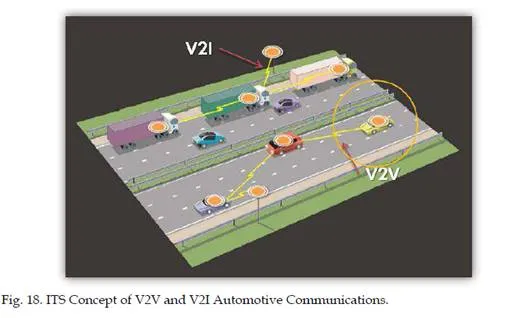
Vehicular telematics are a key technological component of future intelligent road networks. Such systems and technologies offer increased road efficiency, increased safety, improved communications and information services to drivers and passengers, and reduced road congestion and accident rates. Vehicle-to-infrastracture (V2I) or vehicle-to-vehicle (V2V) communication links are likely to be key elements (Fig. 18). Implementation of intelligent transportation systems and applications and vehicular telematics will require demonstration of a number of microwave systems and technologies at an acceptable price per unit. These technologies include antenna arrays, microwave beamforming networks, transmit/receive components, and a variety of sensors, both road and vehicle mounted, in order to increase road efficiency and provide additional services to drivers and travellers. The antennas and beamforming networks are required to provide steered and switched-beam smart radiation patterns to maintain links to moving vehicles and to compensate for signal fading in a complex and dynamic multipath environment. Hence, the development that will be a key to the provision of information-rich and high data-rate services will be microwave systems capable of providing communication links either with roadside beacons (V2I) or with other vehicles (V2V). In the latter case, it will be possible to form wireless vehicular ad-hoc networks (VANETs) with the benefit of reducing communication link range in high traffic density and providing multiple routes between vehicles and roadside beacons.
Intelligent transportation systems also play an important role in the research activities on road safety, allowing vehicles to detect a safety hazard and to react to it timely. Through immediate forwarding of hazard warning information to other vehicles via wireless vehicle- to-vehicle (V2V) communication, other vehicles could avoid running into the hazardous situation. The same wireless communication interface could be used to provide the vehicle with traffic control and road safety information from roadside infrastructure via wireless vehicle-to-infrastructure (V2I) communication. Both V2V and V2I are the basis for ITS framework and applications providing a potential for avoidance of accidents.
In order to ensure efficient allocation of RF resources, it is important to group various V2V- and V2I-based applications in different categories based on their need for radio resources. The first such category is the ITS V2V-based Critical Road Safety Applications characterised by strict time constraints where one vehicle must warn another vehicle of a sudden safety hazard instantaneously. Such ITS applications have strict requirements on communication reliability, tolerable transmission latency, minimum throughput, and medium access delays.
Second category is the ITS V2I based Safety and Traffic Efficiency Applications which are informational applications. These applications may be less time-critical and may benefit from central resource management by roadside infrastructures, more RF link stability due to roadside unit’s static nature, and better antennas. Depending on their unique requirements, Critical Road Safety Applications and Safety and Traffic Efficiency Applications require a higher QoS, such as instant access to RF frequency channel, high SNR and low channel interference, and reliable wireless communication to ensure that the safety messages are received by vehicles with high probability and for both types of applications, microwave beamforming networks based on Butler Matrices and Rotman Lenses can be employed in order to establish a reliable RF communication link among vehicular beacons.
A study was also carried out of Medium Access Control (MAC) protocols which are suitable for V2V and V2I automotive communications. The aim is to be able to communicate within a group of vehicles travelling as a cluster, between vehicles and a roadside transceiver, and from a roadside transceiver in a broadcast mode. Telematics architectures available in vehicular communication and networks are Vehicle Infrastructure Integration (VII) and Communication Access for Land Mobiles (CALM).
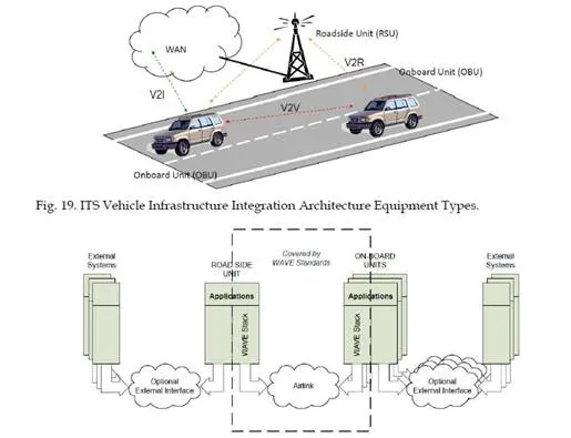
VII architecture seeks significant improvement in vehicle safety, mobility, and commerce by deploying a communication infrastructure on roadways and installing Dedicated Short Range Communication (DSRC) radios on all production light vehicles (Fig. 19). In this scenario, Onboard Unit (OBU) is located inside vehicle, Roadside Unit (RSU) is located on the road and acts as a data gathering and distribution point, control channel broadcasts application and vehicular communication establishment, and service control establishes communication between OBUs and RSUs and between OBUs. Also, DSRC which is a short to medium range communications service that supports both public safety and private operations in V2I and V2V communications is meant to provide very high data transfer rates for mobile wireless nodes in relatively small communication zones and with small latency.
Wireless Access in Vehicular Environment (WAVE) is the mode of operation used by IEEE
802.11 devices in the DSRC band allocated for ITS communication. Fig. 20 shows the WAVE system components. All these advanced wireless vehicular ad-hoc networks (VANETs) can further be integrated with advanced distributed microwave beamforming networks in order
to form a state of the art vehicular network with enhanced performance to serve the ITS framework and objectives. The inherent capabilities of microwave beamforming networks and techniques together with VANETs complex algorithms and architectures will provide a powerful synergy for intelligent transportation systems and vehicular telematics realisation.
Conclusion
The need to relieve traffic congestion and make more efficient use of motorway networks requires a more sophisticated approach to traffic and transportation management. ITS applications and vehicular networks and telematics can offer many benefits using advanced RF and microwave technologies, where vehicles mounted systems communicate with other vehicles or with an infrastructure of roadside beacons. Hence, researches on intelligent transportation systems and applications were carried out to enhance safety and efficiency of road transportation related to vehicle-to-vehicle (V2V) and vehicle-to-infrastructure (V2I) automotive communications. Microwave beamforming networks can greatly increase and enhance the performance of wireless systems used in intelligent transportation systems and framework. In this contribution, passive planar steerable microwave beamforming networks based on Rotman Lens and cascaded Butler Matrices have been designed and analysed in
order to support the wireless systems used in vehicular networks, intelligent transportation systems, and collision avoidance program which includes rear-end collision avoidance system, intelligent adaptive cruise control, road departure collision avoidance system, and lane change collision avoidance system.