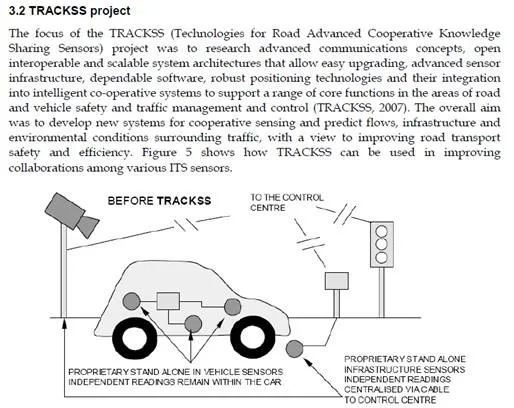
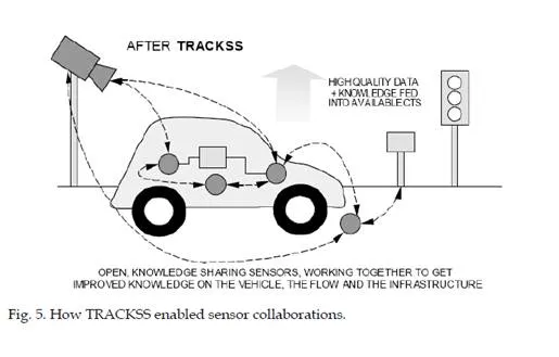
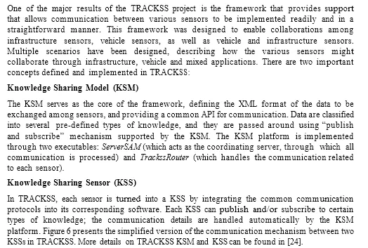
A recent study by the UK Government’s Office of Science and Innovation, which examined how future intelligent infrastructure would evolve to support transportation over the next
50 years looked at a range of new technologies, systems and services that may emerge over that period (UK DfT, 2006). One key class of technology that was identified as having a significant role in delivering future intelligence to the transport sector was wireless sensor networks and in particular the fusion of fixed and mobile networks to help deliver a safe, sustainable and robust future transportation system based on the better collection of data, its processing and dissemination and the intelligent use of the data in a fully connected environment. The important innovations in wireless and digital electronics are beginning to support many applications in the areas of safety, environmental and emissions control, driving assistance, diagnostics and maintenance in the transport domain. The last few years have seen the emergence of many new technologies that can potentially have major impacts on Intelligent Transportation Systems (ITS) (Tully, 2006).
U.S. DOT recently launched a 5 Years ITS strategic research plan to explore the potentially transformative capabilities of wireless technology to make surface transportation safer, smarter and greener and ultimately enhance livability for Americans (US DOT, 2011). This research program formerly known as IntelliDriveSM and now renamed as “Connected Vehicle Research” program which focus to develop a networked environment supporting very high speed transactions among vehicles (V2V) and between vehicles and infrastructure components (V2I) or hand held devices (V2D) to enable numerous safety and mobility applications (US DOT, 2010).
The European Telecommunications Standards Institute (ETSI) has been creating and maintaining standards and specifications for Intelligent Transportation Systems (ITS) include telematics and all types of communications in vehicles, between vehicles (e.g. vehicle-to-vehicle), and between vehicles and fixed locations (e.g. vehicle-to-infrastructure). The ETSI not only looking for road transport domain but also the use of information and communication technologies (ICT) for rail, water and air transport, including navigation systems (ETSI, 2009).
As future intelligent infrastructure will bring together and connect individuals, vehicles and infrastructure through wireless communications, it is critical that robust communication
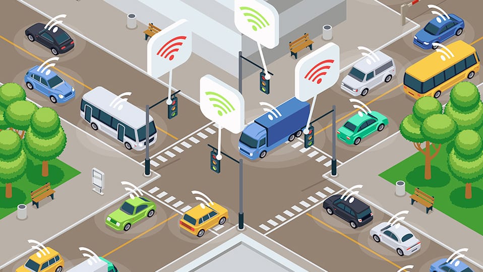
technologies are developed. Mobile wireless sensor networks are self-organising mobile networks where nodes exchange data without the need for an underlying infrastructure. In the road transport domain, schemes which are fully infrastructure-less and those which use a combination of fixed (infrastructure) devices and mobile devices fitted to vehicles and other moving objects are of significant interest to the ITS community as they have the potential to deliver a ‘connected environment’ where individuals, vehicles and infrastructure can co-exist and cooperate, thus delivering more knowledge about the transport environment, the state of the network and who indeed is travelling or wishes to travel. This may offer benefits in terms of real-time management, optimisation of transportation systems, intelligent design and the use of such systems for innovative road charging and possibly carbon trading schemes as well as through the CVHS (Cooperative Vehicle and Highway Systems) for safety and control applications.
Within the vehicle, the devices may provide wireless connection to various information and communications technologies components in the vehicle and connect with sensors and other devices within the engine management system. There is growing consumer demand for wireless communication technologies in transporation applications from point-to-point to multiplexed communications. Advances in portable devices (Smartphone, Personal Digital Assistant and Navigation Systems) may exploit the possibility of interconnection using in- vehicle communications. Also advances in wireless sensor networking techniques which offer tiny, low power and MEMS (Micro Electro Mechanical Systems) integrated devices for sensing and networking will exploit the possibility of vehicle to vehicle and vehicle to infrastructure communications (Blythe, 2006).
Wireless sensor networks offer an attractive choice for low-cost and easy-to-deploy solutions for intelligent transportation applications. Intelligent parking lot application using Wireless Sensor Networks is presented in (Lee et al, 2008). In this paper, authors argue the use of both ultrasonic and magnetic sensors in accurate and reliable detection of vehicles in parking lots. A wireless sensor networks scenario for Intelligent Transportation Systems (ITS) is studied in (Chen et al, 2009) and authors also propose new routing protocol to make the WSN more energy efficient and with less delivery latency.
Wireless Sensor Network based adaptive vehicle navigation in multi-hop relay WiMAX networks is proposed in (Chang et al, 2008). This paper proposes the WiMAX multi-hop relay networks as the inter-vehicle communications to increase the reliability and efficiency of inter-vehicle communications. Real-time traffic information is gathered here from various types of sensors equipped on vehicles and exchanged among neighbor vehicles. Collaboration- based hybrid vehicular sensor network architecture is proposed in (Kong & Tan, 2008). In this paper, authors propose a collaborative hybrid method to deliver desired data to particular drivers effectively. The road side sensors and vehicular mobile sensors are used to restore data and exchange data.
As the wireless sensor networks technology is still relatively new and very little is known about its real application in the transport domain. Our involvement in the transport-related projects provides us with an opportunity to carry out research and development of wireless sensor network applications in transport systems. This chapter outlines our experience in the ASTRA (ASTRA, 2005), TRACKSS (TRACKSS, 2007) and EMMA (EMMA, 2007) projects and provides an illustration of the important role that the wireless sensor technology can
play in future ITS. This chapter also presents encouraging results obtained from the experiments in investigating the feasibility of utilising wireless sensor networks in vehicle and vehicle to infrastructure communication in real ITS applications.
2. Communication technologies
The use of networks for communications between the electronic control units of a vehicle in production cars dated from the beginning of the 1990s. The Controller Area Network (CAN) was first introduced by BOSCH with the clear intent to serve communication systems for automotive applications and it is still dominant in automotive networks. The CAN is not fully satisfying requirements such as predictability, performance and dependability which are mandatory in automotive communications. To overcome the limitations of the CAN technology, a number of technologies have been developed for designing automotive networks such as Time-Triggered Protocol (TTP), Time-Triggered CAN (TTCAN), Byteflight and Flexray (Navet et al, 2005).
Wireless communication technologies such as ZigBee (ZigBee Alliance, 2006), Bluetooth (Bluetooth, 2006 ) and Wi-Fi are also expected to be widely employed in the near future in automotive communication. It is evident that wireless communications can be used in- vehicle, inter-vehicle and between vehicle and infrastructure in transportation applications (Cai & Lin, 2008; Kosch et al, 2009; Heddebaut, 2004). Bluetooth is currently the most widely used automotive wireless technology for in-vehicle communication and Wi-Fi is used for vehicle to vehicle communication by several pilot research projects, e.g., the Car2Car consortium (Car2Car consortium, 2007). Ultra Wide Band (UWB) is an emerging wireless technology that uses a very large bandwidth (Yang and Giannakis, 2004). It is targeted for multimedia networking whereas 802.11 networks address data networking. Intelligent collision avoidance and cruise control systems can be developed using UWB technology as those systems need high ranging accuracy and target differentiation capabilities. UWB technology can also be integrated into vehicle entertainment systems by downloading high- rate data from road-side infrastructure UWB transmitters. Communication Air-interface, Long and Medium range (CALM) (ISO TC204 Working Group, 2007) has many potential applications in V2V and V2I communication.
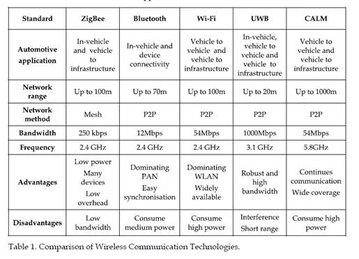
ZigBee will be able to fill the gap left by these other technologies, mainly in the interconnection of wireless sensor devices with vehicles and infrastructure. The ZigBee standard has evolved since its original release in 2004 and it is a low cost low power wireless networking standard for sensors and control devices. ZigBee provides network speeds of up to 250kbps and is expected to be largely used in typical wireless sensor network applications where high data rates are not required. Table 1 shows a comparison between five technologies relating to the most important factors which need to be considered in the ITS application domain.
ZigBee, Bluetooth, Wi-Fi and UWB have been designed for short-range wireless applications with low power solutions and can be used at the in-vehicle and vehicle to infrastructure communication. The ZigBee technology can accommodate larger numbers of devices than Bluetooth. On the other hand, Bluetooth offers high bandwidth with relatively high throughput. Many wireless sensor network applications do not require high data rate communication technology as it is based on data exchange. ZigBee provides 250 kbps data
![]()
![]() rate and is expected to be enough for the many wireless sensor network applications. Notably, ZigBee uses low overhead data transmission and requires low system resources which are vitally important factors for embedded sensor networks. Also mesh networking features in ZigBee protocol allow devices to extend its coverage and optimize its radio resources. The features show that ZigBee is a suitable communication technology for the wireless sensor networks based ITS applications
rate and is expected to be enough for the many wireless sensor network applications. Notably, ZigBee uses low overhead data transmission and requires low system resources which are vitally important factors for embedded sensor networks. Also mesh networking features in ZigBee protocol allow devices to extend its coverage and optimize its radio resources. The features show that ZigBee is a suitable communication technology for the wireless sensor networks based ITS applications
3. Smartdust in transportation applications
Smartdust (or mote) is a new concept for wireless sensor networks which offers tiny, low power and MEMS integrated devices for sensing and networking and it’s also known as “motes”. It is not only interesting for the low power sensing technologies but also the low power communication and networking capability which it has demonstrated (Tully, 2006). Fundamentally, it provides a convenient and economic means of gathering and disseminating environmental and other useful information in the transport domain. Existence of ZigBee based networking capability between Smartdust and other devices will benefit many low cost and low power applications in the ITS. Smartdust devices also have sensors attached to them to monitor the physical environment in some way. These sensors can be built directly onto the Smartdust or can come as daughter-boards which can be connected in some way to the motes main motherboard. Sensors can measure a wide range of environmental parameters, such as pollution, noise, temperature, humidity as well as vehicle speed, vehicle direction and vehicle presence. Initial studies suggest environmental
monitoring, vehicle to vehicle, vehicle to infrastructure and infrastructure to infrastructure applications may exist for Smartdust in the transport domain. Indeed the vital application of the devices is beginning to be tested in the road vehicle environment. Even though a range of Smartdust platforms are available in the market, Crossbow Mica (Crossbow, 2006) family motes will be discussed here due to their commercial success in many wireless sensor network applications.
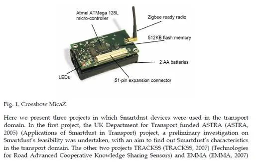
Mica family motes can be programmed with NesC based TinyOS (TinyOS, 2006) , C based NanoQplus (NanoQplus, 2008) and many other operating systems which are designed for embedded systems with very limited resources. Also, MicaZ mote will be the most suitable platform for the wireless sensor networks based ITS application since it features sensing and networking capabilities with low power consumption using ZigBee as communication protocol. Figure 1 shows a Crossbow MicaZ mote. The MicaZ mote is a family of the Crossbow Mica motes where the radio transceiver uses the Chipcon CC2420 IEEE 802.15.4 (ZigBee) compliant chipset. This will allow the MicaZ motes to communicate with other ZigBee compliant equipment. The software stack includes a MicaZ mote-specific layer with ZigBee support and platform device drivers, as well as a network layer for topology establishment and single / multi-hop routing features. The MicaZ mote platform is built around the Atmel AtMega128L processor which is capable of running at 7.37 MHz. The MicaZ motes have 128 Kbytes of program memory, 512 Kbytes of flash data logger memory, and 4 Kbytes of SRAM. Power is provided by two AA batteries and the devices have a battery life of roughly 1 year depending on the application (very low duty cycle assumed). Sensor boards can be attached through a surface mount 51 pin connector, Inter-IC (I2C), Digital Input Output (DIO), Universal Asynchronous Receiver Transmitter (UART) and a multiplexed address/data bus.
(Embedded Middleware in Mobility Applications), both were EC FP6 funded) built on the information gathered from ASTRA project by implementing several ITS applications using Smartdust. The TRACKSS project focussed on achieving this through collaboration between Smartdust and other sensing technologies, whereas the EMMA project designed and implemented a middleware that enables integration of Smartdust with heterogeneous sensor platform in the transport domain.
3.1 ASTRA project
The ASTRA project investigated the use of mobile wireless sensor networks, and more specifically, Smartdust for transport applications. The project examined the current state-of- the-art with Smartdust devices, using MicaZ and Mica2 motes as the technology to be tested. It also looked at the likely market and technological advances of the Smartdust technology over the coming decade.
3.1.1 ASTRA project trials
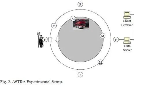
A trial using Smartdust technology was hosted in Newcastle with a pervasive intelligent corridor established by a network of fixed motes on roads near Newcastle Central Station. Mobile motes were also placed in several buses. Communication between a static mote and a moving mote on-board a vehicle was achieved, showing that communication can take place between road side and vehicles using a network of motes. The architecture consisted of a number of Fixed motes (F) attached to bus stops along a circular bus route and a number of Mobile motes (M) carried by buses travelling in both directions along this route. One special fixed mote was placed in an interface board connected to a Data Server PC. The PC was connected to other Client PCs via the Internet. The range of the motes was such that it was unlikely that fixed nodes would always be able to communicate directly. They communicated with mobile nodes as buses passed bus stops. The buses communicated with each other as they passed. Together, the fixed and mobile nodes formed an ad-hoc network.
The motes were concentrated in an area of Newcastle close to the Central Station, as shown in Figure 3 below. The red dots represent the bus stops which carried the motes. The buses travelled along Grainger Street and Neville Street before crossing the River Tyne to Gateshead (as seen in the map). The PC which acted as a Data Server was located in the Centre for Life, in the lower left-hand corner of Figure 3.
3.1.2 Experimental results
In an urban road environment radio wave reflections from surrounding buildings and objects can have a significant impact on the performance of the radio. In some situations the performance of the radio is enhanced and in other situations the performance is reduced. Reducing the motes radio transmitter power is likely to improve the performance of the radio in some cases due to a corresponding reduction in the number of radio wave reflections. Possible future research includes developing a way for motes to adjust their radio power to obtain optimal radio performance at a given location.
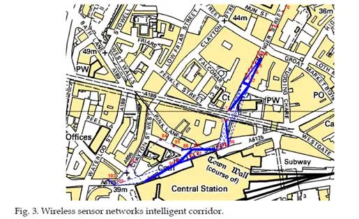
The map is presented above is the Central Station area which shows the quality of each link. The quality of a link is based on the percentage of packets received, the higher the percentage the higher the link quality. This is indicated on the map by varying the width of the line between points where larger widths indicates higher quality links. A dashed line indicates total packet loss. The results also show that the distance between nodes is not the only factor in determining link quality. Radio reflections and interference seem to have played a significant role in determining the link quality during this experiment. Many of the shorter links did not show any connection whereas some longer links showed a good quality connection.
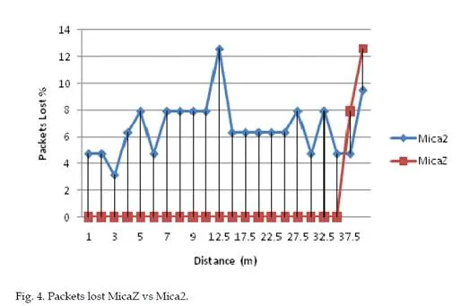
Experiments also showed that the MicaZ motes outperform the Mica2 motes in rural and urban environment due to their improved radio performance. Deploying MicaZ motes as
opposed to Mica2 motes may therefore require fewer motes to cover the same geographical area. Matching the correct motes for the environment in which they are used will clearly be important. Although not tested within the trial, it is reasonable to conclude that the use of Wi-Fi or Bluetooth would result in a worse performance than using ZigBee as the former two technologies carry a greater overhead for new nodes joining a network.
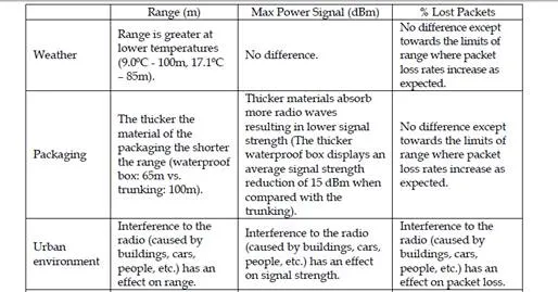
Several experiments showed that it is possible to create connections between moving vehicles and a roadside infrastructure in an urban environment. It was also possible vehicles travelling at high speed (70mph). The time available for data transfer during a passage is a function of the radio range, the speed of the vehicle and the overheads involved in having the mobile node join the network. The ASTRA trial findings are summarized in Table 2.
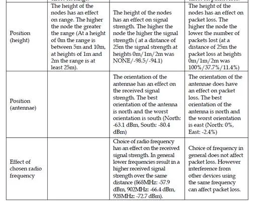
Experiments were carried out to investigate the effect of mote packaging, height, antennae position and position inside the vehicle (Bus/Car) in radio range, received signal strength (RSSI) and packets loss. The experiment results showed these parameters have a significant effect on radio range and packets loss but can be overcome transmitting packets with high power level or using many devices to form a network (multi-hop technology). Experience gained from the ASTRA project trials provided the opportunity to use Smartdust devices in a range of transport prototype applications in the TRACKSS and the EMMA project. It seems that the opportunities of using Smartdust as part of a connected world (collaboration with other sensors/platform) for future intelligent transportation system are high.
In this paper, one of the TRACKSS collaborations involving Smartdust and Near-Infrared
Optical Identification sensor is presented.
The Near-Infrared Optical Identification sensor was developed by LIVIC-LCPC (France) and its purpose is to detect, identify objects (i.e. vehicles or roadside objects) and localize them in the road scene. It is composed of two parts: an Emitter part and a Receiver part. The Emitter, which is the active part, is a near-infrared LED-based lamp, which, thanks to an embedded controller, codes an identifier (a number) using a defined frame protocol. The signal is thus time-coded (blinking light) and not space-coded. This enables important improvements with regard to detection ranges and robustness when compared to traditional spatial-pattern- based identification systems. The Receiver is a high-frame-rate, low-resolution CCD camera, equipped with an IR-bandpass filter, plus a decoding algorithm. By attaching an Emitter (with its unique identifier) to an object (such as a road sign), the Receiver can detect,
identify, and locate it on the road scene. Full details of the Near-Infrared Optical
Identification sensor can be found in (von Arnim, 2007 and 2008)
This collaboration was implemented using the support provided by the KSM and its executable platform, turning the Smartdust and the Near-Infrared Optical Identification sensors into two collaborating KSSs. Among others, this collaboration enables a more robust Road Sign Recognition Application to be implemented, where one sensor’s capabilities can complement the other’s weaknesses. This is based on the fact that no individual sensor is perfect: each has its own features and limitations. In this case, the Near-Infrared Optical Identification sensor has a very good range and localization features, but it relies on visual detection. This makes it prone to errors when objects may obstruct the view, or in inclement weather conditions. On the other hand, the Smartdust sensor cannot easily determine the location of a target (since it relies on radio signal, which does not necessarily carry the information on the detection direction), but the radio signal is free from visual impairment. By combining the positive characteristics of these two sensors, we have developed a new system that provides a more robust detection and identification of objects on the road.
3.2.1 Cooperative road sign detection application
By attaching the Smartdust transmitter and the Near-Infrared Optical Identification sensor Emitter to a road sign, suitably equipped vehicles can detect, identify, and localize the road sign ahead with sufficient time and even in poor visibility. For this application, we equip a car with a Near-Infrared Optical Identification Receiver (camera), a Smartdust device (sitting on its base station), and a computer connected to these sensors, on which the applications controlling these sensors are running. We also place infrared Emitters and Smartdust devices next to the sign on the side of the road; they act as the broadcaster of signal for representing the road signs. Figure 7 provides a diagrammatical representation of this set-up.
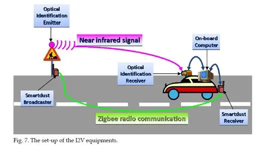
On the on-board computer, both sensors communicate using TRACKSS’ KSM. Essentially, the KSM serves a middleware that encapsulates a common communication protocol of these two sensors, enabling them to exchange information in a straightforward and uniform manner. This collaboration combines the long detection-range capabilities of the Near- Infrared camera with the visual-independence feature of the Smartdust in order to develop a more robust system for road sign detection.
In most cases, the Near-Infrared camera picks up the signal from the infrared Emitter prior to the Smartdust base station picking the signal from the Smartdust device on the side of the road. In these cases, the latter provides a confirmation of the detected road sign to the former, hence increasing the confidence of the result. In other cases (for example, around the bend or if there is some visual impairment), the Smartdust picks up the road sign signal before the camera. The system will then warn the driver that a road sign is detected nearby, but we do not have 100% certainty until this is confirmed by the camera.
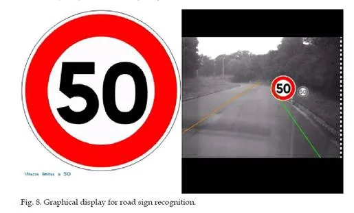
Two examples of graphical displays can be seen on Figure 8. The left one shows a symbolic representation of the road sign and the right one show an “augmented reality” view, where the road sign is drawn at its real position on the image. One can easily understand the benefit of this application for night-time driver assistance. Further details of this collaboration – along with details of several other collaborations – can be found in (Arief & von Arnim, 2008, von Arnim et al, 2008).
3.2.2 Experimental results
The first major experimental result of this application is given by the fusion of identification information from two different sensors with different technologies. When the fusion
strategy is a confirmation of one sensor by the other, then the limitations of each sensor can be compensated.
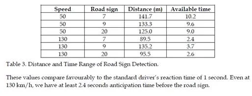
Concerning the detection range, with our confirmation strategy (where the target must be within range to be simultaneously detected by both sensors), the final range is highly influenced by the range of either sensor, depending on weather conditions. The Near- Infrared Optical Identification sensor has a much higher range than the Smartdust sensor in its best-case scenario (low-luminosity). On the contrary, in the worst-case scenario for Near- Infrared Optical Identification sensor (sunny weather), the Smartdust usually has greater range. Another interesting observation is that the Near-Infrared Optical Identification sensor performs better when the vehicle is travelling at a high speed whereas Smartdust is better at low speed. So to sum up, both sensors complement each other in their capabilities. Our applications do not need a range over hundreds of meters. The fused sensors need to be able to detect a road sign sufficiently early to warn the driver or start an action, at any speed up to 130km/h. The ranges measured in both scenarios are sufficient. It is also important to note that the range of the Smartdust sensor can be easily increased by chaining multiple Smartdust sensors in an ad-hoc network ahead of the road sign. It is therefore possible for both sensors to have a comparable detection range.
From these detection range data, we can also derive information about the “distance-to-be- covered and available-time before passing the road sign”. This value is very much affected by the speed of the vehicle; Table 3 shows the values at two different speeds: 50 km/h and
130 km/h. The road sign ID relates to the identification number of the road signs – in this case: 7 (representing a danger sign), 9 (representing an end of 50 km/h speed limit) and 20 (representing a traffic light).
3.3 EMMA project
The EMMA (Embedded Middleware in Mobility Applications) project (EMMA, 2007) had an overarching goal of utilising new embedded middleware to support the underlying logic and communications required for future cooperating wireless objects and the applications they may support in the automotive and road transport domains. The EMMA project was committed to deliver a middleware platform and a development environment which facilitates the design and implementation of embedded software for cooperative sensing objects. The ultimate aim of the project was to hide the complexity of the underlying
infrastructure whilst providing open interfaces to 3rd parties enabling the faster, cost- efficient development of new cooperative sensing applications.
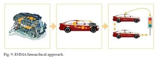
The EMMA network architecture can be considered at three levels (Figure 9): Within an automotive subsystem, at a vehicle level and at the supra-vehicle level. Recently, many wireless micro sensor network applications are being developed for a variety of applications including transport monitoring and control. However, there are still numerous challenges to be overcome if wireless sensor devices are to communicate with each other in an intelligent, cost effective and reliable way. The EMMA project selected the principle of hierarchical Wireless Co-operating objects (WICOs). The number and type of objects present in any given WICO hierarchy may vary depending on the prevailing conditions and their availability; however the handling of this can be abstracted away from the application developer by the middleware wherever possible.
It was necessary to find suitable technologies to support and coordinate WICOs at all three levels. Given this wide variety of sensor technology available and in common use, a popular approach to manage the growing complexity of a typical development is to create a malleable interface often called termed middleware. Middleware has been around for many years in different forms. “Middleware” in the loosest terms covers a wide variety of system integration schemes.
Evaluation of many middleware technologies has often reached the conclusion that middleware is a large and complex system, requiring careful coupling to, and tuning for, the specified application domain (EMMA, 2007). As a result there is a need to identify and develop a middleware system optimised for the challenges present in the intelligent transportation domain. A differentiating factor between current middleware models and the proposed EMMA system is the need to operate on multiple different platforms, with substantially different resources available.
Current middleware technology is typified by systems designed to run in non-real time, resource rich environments, such as large business information systems. A typical traffic infrastructure or automotive application runs in a real-time environment with strictly limited resources, distributed across many control units, themselves incorporating multiple dissimilar sensors (Hadim and Mohamed, 2006, Katramados et al, 2008).
EMMA middleware is capable of integrating systems for transportation application using large powerful fully featured PowerPC based FPGA technology (Xilinx ML403) which uses Qplus operating systems, as well as compact, battery-powered Smartdust devices which uses NanoQplus operating systems. An additional capability of the EMMA middleware is the ability to handle dynamic, ad-hoc networks. These are a natural result of communications between moving vehicle-based environments and infrastructure systems with finite static coverage. It must be possible to handle the potential changes to the network composition whilst insulating the application developer from the technical challenges that this involves
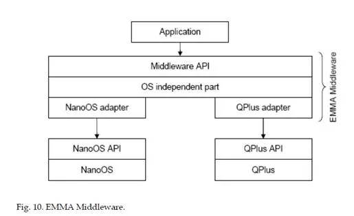
The core part of the middleware is independent from the operating system and platform it is running on. This part provides several functions to the application through the middleware API. Since the different platforms vary strongly in resources like memory size, energy or CPU speed, not all functions will be provided on all platforms. The OS independent part, therefore, has to be modular. The adapters also include conversions for the APIs of different communication technologies, e.g. ZigBee or CAN. Each communication technology uses, for example, a different addressing scheme that has to be hidden from the EMMA applications. Therefore, the middleware defines an independent addressing.
The EMMA middleware is designed in a modular fashion. The communication adapters form the interface between the communication module and the actual hardware drivers. The communication module has a generic part and two specialised parts for message and data- centric communication (Yang & Wang, 2007). The detailed description of each of the modules is provided below.
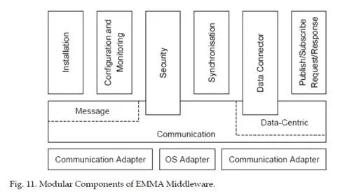
Security is also an integral part of any ITS application which can be achieved with the combination of three core components, namely authentication, encryption and mechanisms for access control. The EMMA middleware provided both conceptual support for pre- distributed symmetric keys and conceptual support for symmetric encryption but no support for access control mechanism. Another FP7 funded PECES (PECES, 2009) project (a follow-up project of the EMMA project) is currently developing a complete security suite for pervasive computing applications including transport domain. The PECES project security suite make use of existing encryption protocols and standards to ensure the authenticity of devices, to exchange encryption key between communicating devices and to provide appropriate access control mechanisms to limit information sharing in and between devices. More detail information about PECES project security concepts can be found in PECES project Secure Middleware Specification deliverable (Handte et al, 2010).
The security module in the EMMA middleware provides management of keys and encryption and decryption function. The actual functions that perform encryption and decryption have to be provided by the application developers but the EMMA middleware provide mechanisms for calling them at the right time. Before a received message is delivered to the application, the security module is called to decrypt the message using the provided key and decryption function. Conversely, it is also called before handing over the message to the communication layer for sending.
In the road infrastructure domain, the scalability of the EMMA middleware allows it to be embedded in a variety of platforms from tiny Smartdust sensors to traffic control systems. By developing these devices using a common middleware based platform, the individual Smartdust devices can be configured as Wireless Cooperating Objects (WICOs). This WICO based sensor network allows the system to be flexibly configured to take advantage of changing conditions, for example with transitory sensors joining or leaving the fixed network as appropriate. The EMMA middleware provides a whole new range of opportunities for exchanging data amongst different vehicle sensors, subsystems and the
engine. Numerous applications are continuously being developed aiming to improve the safety and enhance the driving experience. However, often such systems are isolated from the rest of the vehicle and their sensor information cannot be reused. As a solution, the EMMA middleware transforms such sensors to cooperating objects, giving the opportunity to develop new data fusion applications.
3.3.1 Vehicle to infrastructure application
Applications were developed in order to demonstrate the benefits of the middleware for giving priority to emergency vehicles. For the infrastructure level application, an emergency vehicle (ambulance, fire engine or police car, etc) are equipped with a Smartdust WICO (or a MicaZ mote installed with the EMMA middleware) which broadcast a beacon message if it is on an emergency situation. For example, in a busy intersection controlled by traffic lights, emergency vehicles are detected and given priority by regulating the state of the traffic lights (Figure 12).
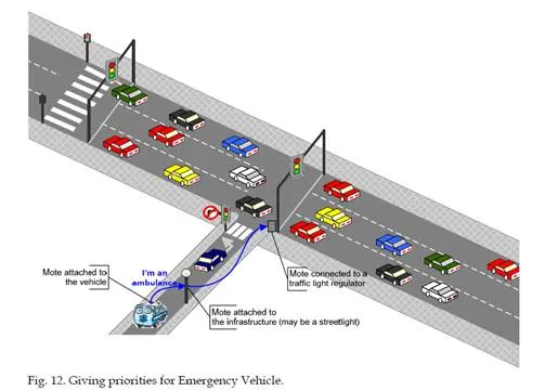
communication mechanisms (publish/subscribe) and other time periods the traffic regulator needs in order to guarantee safety first. The traffic regulator has been programmed to attend to the trigger signal provided by the mote activating an emergency control sequence. The demonstration has successfully carried out real road environment in Valencia, Spain.
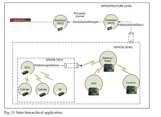
An inter-hierarchical application, integrating all three levels that developed in the project: the automotive subsystem, the car level and the supra-car level, was also developed to demonstrate how heterogeneity issues can be solved in wireless sensor networks developing EMMA middleware. In this application demonstration, inter-hierarchical collaboration of the WICOs developed on the project consisted in transforming the information provided by the vehicles at both engine level (cylinder pressure and oil pressure sensors are based on TelosB platform) and vehicle level (GPS, Vehicle dynamic and Radar sensors are based on Xilinx ML 403 platform (Katramados et al, 2008) ) into specific traffic control actions at infrastructure (to Smartdust WICO) level. In the infrastructure, a Smartdust WICO was connected to a portable VMS to display the information sent by the engine level and vehicle level sensors. The inter-hierarchical application scenario is explained in Figure 13 with the EMMA middleware components.
The above application scenarios were implemented and tested with the EMMA middleware. This was used as a test bed to check the correct operation of EMMA approach for wireless sensor networks. It is worth mentioning that wireless pervasive computing applications for
ITS can be developed using the EMMA middleware but validation of such scenarios would require an extensive use of cooperative transport systems which is out of scope of the EMMA project. The EMMA middleware aims to provide an efficient platform to develop embedded applications for future intelligent transportation systems. The big advantage is that the EMMA approach is completely open to any systems and easily adapt to different applications.
3.3.2 Experimental results
Several set of experiments have been carried out with the EMMA middleware to evaluate possible use of Smartdust WICO in the supra-vehicle level as well as engine level and vehicle level application. These experiments intend to evaluate the use of wireless sensors with the EMMA Middleware for the proposed application scenarios at three different hierarchical levels. The engine level and vehicle level sensors are static networks and experiments showed satisfactory results for the application. The following section provides some experiments of the vehicle to infrastructure scenario. Two Smartdust WICOs were used and the first WICO was programmed with the EMMA Send message component and this WICO transmitted a packet for every, 500ms and 1000ms. The second WICO was programmed with the EMMA receive message component and connected to the MIB520 programming board which in turn was connected to a Laptop computer.
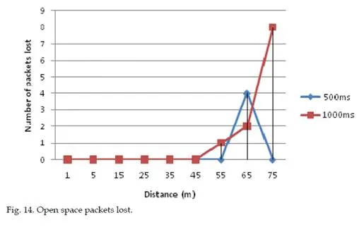
Open space experiment
This experiment was carried-out on the Exhibition Park, a large grassy area to the north of the Newcastle University. Each scenario, 100 packets were sent and those packets were received. Both WICOs were placed at 1m above the ground. The WICOs power level was set to maximum level. Each scenario repeated three times and calculations were performed offline to determine how many messages were lost at each distance and average values reported in Figure 14.
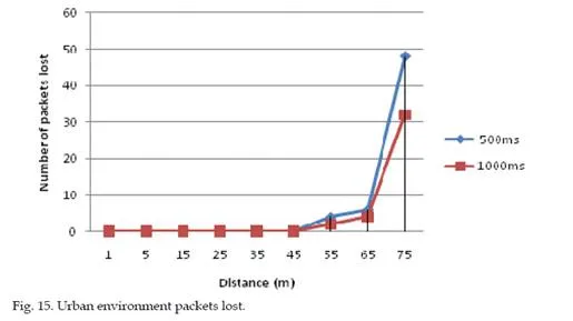
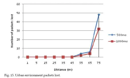
Urban environment experiment
This experiment was carried-out on the Claremont Road, a busy road near to the Newcastle University. Each scenario, 100 packets were sent and those packets were received. Both WICOs were placed at 1m above the ground. The WICOs power level was set to maximum level. Each scenario repeated three times and calculations were performed offline to determine how many messages were lost at each distance and average values reported in Figure 15.
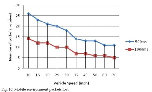
Mobile environment experiment
This experiment was carried-out on the Claremont Road up to 40mph and at the Motorway near to the Newcastle airport for higher speeds. The first Smartdust WICO was placed on a road side stand 1m from the ground and the second Smartdust WICO was placed on the middle of the dashboard of a vehicle. The Smartdust WICO at the vehicle sent message periodically which was received by the Smartdust at the road side. Each scenario repeated three times and calculations were performed offline to determine how many messages were lost at each distance and average values reported in Figure 16.
The open space experiment and urban environment experiment show that packets can be received without any packet lost up to 45m distance. The percentage of packets lost increases above 45m distance in both cases. In the mobile environment experiment, the received packets decrease with the speed increases as the WICO is in range for a shorter period of time. This means that communication time window decreases with the vehicle speed. At the 70mph speed, The WICO in the roadside received 5 and 11 packets for sending intervals 1000ms, 500ms respectively. And interestingly, there was no packets lost were seen between the first packet and the last packet received. The mobile environment experiment demonstrated that Smartdust WICO can be used with the EMMA middleware
communication methods between a fixed infrastructure WICO and also fast moving vehicle-based WICO applications. This is an important finding which proves that the ZigBee Smartdust WICO do not suffer from any Doppler effects at normal motorway (70mph) speeds. It shows that the EMMA middleware communication functionality works well even the vehicle travelling at 70mph.
4. Discussion
This chapter has summarised the research undertaken at Newcastle University to investigate the use of Smartdust devices for Intelligent Transportation System Applications. The costs of building and maintaining the infrastructure could be amortised over many such services delivered by Smartdust based wireless sensor networks. Research to deliver this concept of connected mobile devices and infrastructure leads to the opportunity to consider realistically for the first time a fully connected Intelligent Transport System for the future.
Research is currently focused on filling in the knowledge and technology gaps in pervasive, mobile ad-hoc wireless systems for a range of transport applications. Mobile wireless systems are beginning to be proven as a future tool that will enable the joining up of vehicles, individuals and infrastructure into a single ‘connected’ intelligent infrastructure system. Embedding this technology in infrastructure – such as environmental sensors in lampposts, embedded in vehicles and infrastructure, in goods, and even connecting individuals through their Smartphones, or even bespoke wearable wireless interfaces – offer potential for a more all-seeing, all knowing ITS infrastructure. If for example, vehicles are continually in wireless communication with the infrastructure, new paradigms for traffic monitoring and control could be considered, road space allocated more efficiently and incidents dealt with in an optimum way. If vulnerable users have such wireless devices, the infrastructure could warn vehicles to slow down and the drivers to be more vigilant –
indeed wireless devices attached to children could for example warn drivers that children are playing out on the street, just around the corner and to reduce speed now. Such devices could help with security and safety of individuals, be used on airline boarding cards and other tickets, and even be used to verify HOV (high occupancy vehicles) or blue badge entitlement. When such a system is also connected to say, a vehicle’s CAN-bus, then information on driving style, strange driving behaviour (say where there is a badly maintained stretch of road or object in the road, could be detected from the CAN data – allowing mitigating and maintenance actions to be automatically triggered).
Many of these devices can carry payloads such as sensors, and the idea of monitoring pollution with these devices in a pervasive way is beginning to be researched by Newcastle University (with pervasive wireless environmental sensors being attached to lampposts). However if these devices become small and cheap enough (as is the future vision for Smartdust) then one could image that we each carry our personal exposure meter. Moreover with ‘extreme’ sensor design, wireless pollution sensors could be fitted in engine manifolds and exhaust pipes to allow the actual pollution generated by a vehicle to be measured and maybe adjustments to driving style or engine management systems can be advised or made to mitigate some of the pollution effects (early prototypes are being developed at the university at the moment). If future ‘carbon allowances’ are to be considered in the connected car, the pollution the car generates will also need to be measured and monitored
– as proposed in the Smart Market Protocols project where auction and trading-based carbon allowances have been considered.
Significant research is required to fully realise the potential of such wireless systems, not just on the transport application side, but challenges to reduce the size of these devices from
‘smart-lumps’ to ‘Smartdust’ is critical as size, cost and power consumption of these devices will dictate whether the devices will become pervasive in the transport domain. This requires detailed work on antennae design, an investigation as to which is the most appropriate communications frequency, 802.11x, the influence of CALM, Wi-Fi and probably the most important challenge being battery power requirements (using power scavenging or other techniques).
The final key area of research which is still embryonic is in low-cost and robust sensor design – much work is on-going but uncoordinated in the transport domain. The robustness and dependability of mobile sensor devices, suitable communications protocols and e-science techniques to deal with the data are crucial. Also important is the issue of privacy and data protection in a potentially all-seeing, all-knowing connected world, which rise the question of how much information we want, need and what level of intrusion are we willing to bear.
5. Conclusion
It is clear that the next generation of vehicles will be required to have increased safety, lower emissions and more entertainment with higher performance than those of today. The innovations in wireless sensor devices and digital electronics will enable novel automotive applications which will become very common in future ITS. The challenges such as integrating heterogeneous devices for specific ITS application can be achieved by developing technologies such as in the TRACKSS and the EMMA projects.
This chapter has presented research projects that has been undertaken to investigate the suitability of using Smartdust and ZigBee technology for the intelligent systems applications. A selection of the applications and experiments carried out to systematically characterise the Smartdust technology in the road domain were presented here. The ability to communicate between vehicle and roadside illustrates that Smartdust will enable efficient and discrete communications between vehicle and roadside infrastructure – as the unit cost of Smartdust devices will continue to go down – this is a significant contribution to the ITS domain.
Comments are closed