Electromechanical oscillations are natural phenomena in power systems having two or more synchronous generating units operating interconnected. These oscillations are undesirable because they can severely limit the power transfer between interconnected generating areas, due to reduced stability margins, as well as may decrease lifetime expectancy of system machines. If these electromechanical oscillations are not satisfactorily damped, they may, under some operating conditions, even increase (in amplitude), causing shutdown (tripping) of one or more interconnected generating units. As the oscillations are related to the physical nature of the electrical power system component’s interactions, they cannot be avoided. However, by using efficient automatic control techniques, the electromechanical oscillations can be sufficiently attenuated in order assure a safe system operation, for all allowed operating conditions [1, 2].
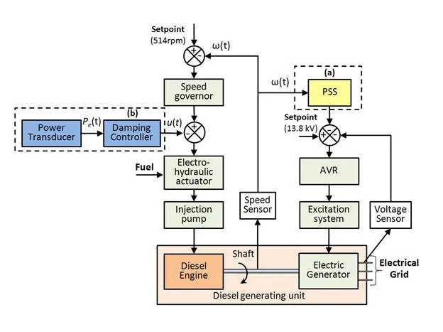
Among the devices utilized to deal with electromechanical oscillations, the most common are the power systems stabilizers (PSS). As can be seen in Figure 1, dashed box (a), PSS devices usually actuates through the automatic voltage regulator (AVR) in order to increase the damping of poorly damped oscillations modes. The improvement of the damping is obtained through a torque component proportional to the machine speed deviation [1, 2].
An alternative technique, which has been investigated by several authors [3-5], is the application of a damping controller through the speed governor system (see dashed box (b), in Figure 1). This is the approach followed by this work. It is important to remark that this technique is recommended only for generators systems having fast response actuators, such as diesel engines. The installation of a damping controller via the speed regulation system may be advantageous because theoretical studies show that there is a weak coupling between this control loop and excitation system controllers in other machines of the interconnected power system [3, 4].
A complete real world example of a control development for safe operation of a power plant has been presented in this chapter. The chapter details the design, implementation and field tests of a digital damping controller applied to a diesel generating unit, at Santana thermoelectric power plant (located in north of Brazil), addressing the system identification and the implementation of the damping controller using digital control techniques. The experimental tests results are presented and discussed.
System description
DIESEL GENERATING UNITS AT SANTANA POWER PLANT
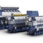
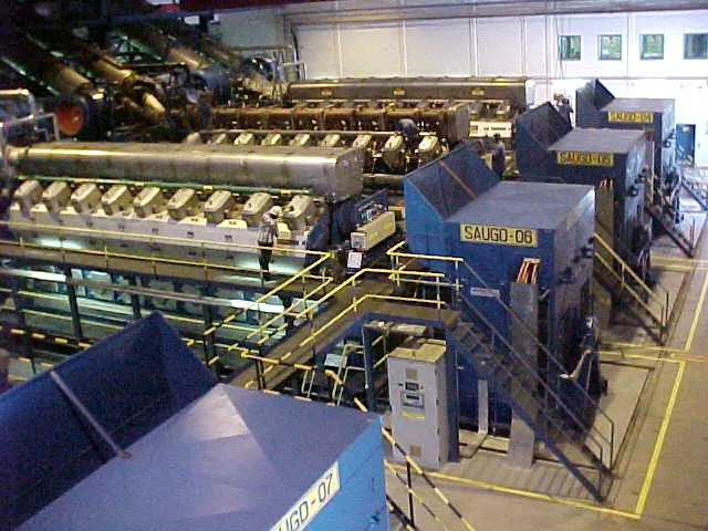
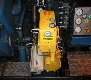
Santana Power Plant has a set of seven generating units, including four identical 18-MVA Wärtsillä diesel generating units (Figure 2). Due to economic operation constraints, it is advisable to preferentially operating the diesel engines because these machines have the lowest specific fuel consumption among the power plant generating units.
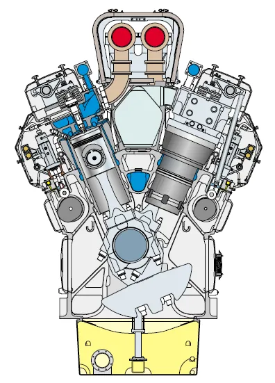
The diesel generating units are driven by 18V46 Wärtsillä four-stroke diesel engines, which have 18 cylinders in V-form (V-angle of 45°), as shown in Figure 3. The engine presents a turbocharged and intercooled design, along with direct injection subsystem.
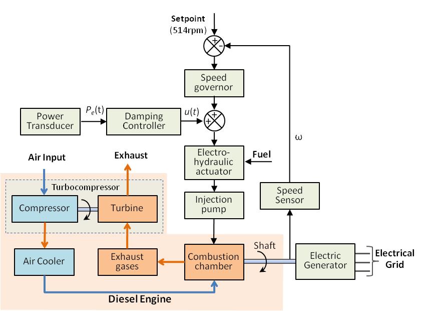
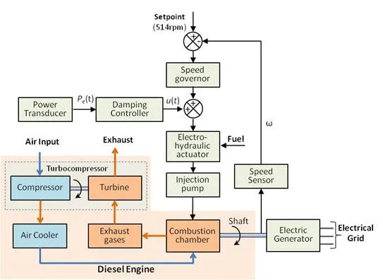
A simplified block diagram of the diesel generating units is shown in Figure 4. The turbocharging is performed by turbocompressors, which are driven by the exhaust gases from the combustion chamber. The turbine drives the compressor subsystem which in turn draws air from the environment increasing the air pressure. The compressed air is then cooled and, subsequently feedback into the combustion chamber, as illustrated in Figure 4. In order to keep the rotor speed at nominal value, during the system operation, a speed governor controls the loading of the diesel engine by actuating on the electro-hydraulic actuator position (see Figure 4). Therefore, more or less fuel is injected in order to increase or decrease the mechanical power demanded by the electrical generator and its load.
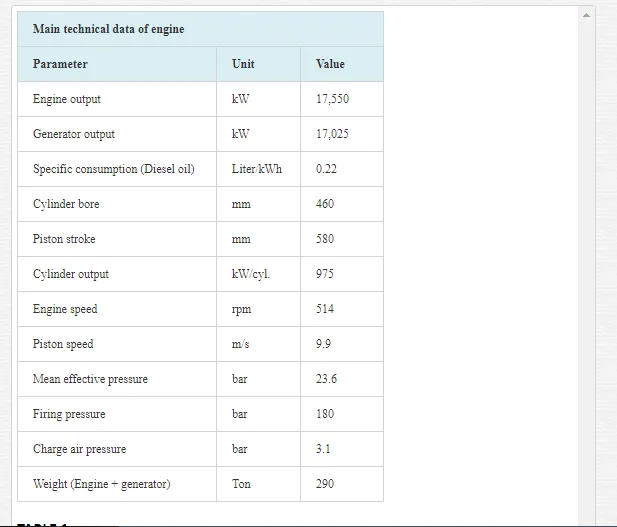
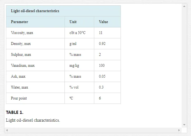
The damping controller proposed in this chapter actuates in the output of the speed governor, modulating the electro-hydraulic actuator position according to the observed electromechanical oscillation on the measured electric power. Table 1 shows the main technical characteristics of the 18V46 diesel engine:
Depending on fuel availability, the 18V46 Wärtsillä diesel engines can be feed by one of the following fuel types: light fuel oil (light oil-diesel), heavy fuel oil, and natural gas. In Santana thermoelectric power plant, the light oil-diesel is the preferential choice. The light oil-diesel characteristics are presented in Table 2.
The fuel injection system is composed of injection pumps, high pressure pipes, and injection valves. The nozzle is located at the top center of the cylinder head. The pressurized fuel in the low-pressure oil line (8.0 to 11.0 bar) has its flow controlled by the electro-hydraulic actuator, which is driven by the output signal of the speed governor (Figure 5). The fuel injected into the high-pressure combustion chamber (180 bar) is atomized and the combustion occurs after the compression cycle.
LOW-DAMPED ELECTROMECHANICAL OSCILLATIONS
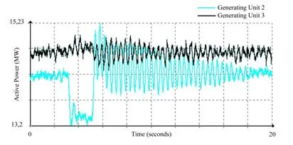
Based on a priori information, provided by utility technical reports [7], a dominant 2.5 Hz intra-plant electromechanical oscillation mode was identified having a much reduced damping, which was observed from the measured machine terminal electrical power signal (Figure 6), when was applied a step in the electro-hydraulic actuator of the generating unit 2. As can be seen, diesel generating units 2 and 3 (G2 and G3) oscillated on phase opposition, which is interpreted as an indicative of intra-plant oscillation mode [2]. These tests were performed in order to investigate the reasons for the frequent machine shutdown (trip) due to actuating of torsional mode protection. Based on this a priori information, the 2.5 Hz intra-plant oscillation mode was then chosen as the target oscillation mode for which the digital controller presented in this chapter was designed.
Digital damping controller
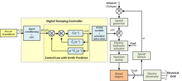
In order to perform the field tests, the damping controller was implemented on an embedded system, composed by the main blocks: input conditioning system, digital controller, actuation system, local HMI, and communication interface (Figure 7).
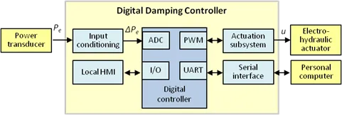
In order to obtain a signal having enough information about the dominant power oscillation, it was necessary to pre-processing the measurement data. To that end, the active power signal (Pe) has been chosen as the feedback signal to the damping controller. This choice was based on field tests, which indicated that the signal/noise ratio can be improved. Therefore, the Pe signal was applied in the conditioning module, where it was filtered by a first-order low-pass filter in order to attenuate noise and, after that, the signal was processed by a first-order high-pass filter (washout) in order to eliminate the DC component.
The digital processing module of the damping controller is based on a digital signal controller (DSC). This device incorporates features of microcontrollers (variety of internal peripherals) and the DSP’s (specific support for digital signal processing). The analog signal ∆Pe is converted to digital through an internal 12-bits analog-to-digital converter (ADC). The firmware of the proposed damping controller control law was embedded in the digital signal controller and its control law was programmed by using C language.
The output of the digital controller is generated through an internal pulse width modulation (PWM) module of the DSC. The action of the damping controller in the electro-hydraulic actuator of the diesel engine is achieved by means of an actuator subsystem, which modulates the output current of the speed regulator. This electronic sub-system is implemented as an array of power transistors, which composes a current mirror scheme, which is commanded by the PWM signal.
The communication between the embedded system and other devices is performed through a RS-232 serial interface. Through this communication link, the embedded system is able to transmit the collected data to a personal computer (PC), to perform analyzing and control.
The developed embedded system was designed to operate in four different operational modes, namely: (i) “step response”, (ii) “identification”, (iii) “control”, and (iv) “configuration mode”. When in the first mode, the equipment applies a step variation to the electro-hydraulic actuator, collect the plant response and send the collected data to an auxiliary microcomputer PC, for a more complex data analysis. When operating in identification mode, the damping controller may generate a pseudo-random binary sequence (PRBS) and uses this signal test to modulate the electro-hydraulic actuator position of the diesel engine. Using a non-recursive least mean squares algorithm, pairs of input and output data are used to obtain plant estimated parametric models, which are used on the controller design. When in “control mode”, the damping controller acquires the signal of active power deviation and processes the damping control law, generating a control signal that is applied in the actuator of the fuel valve of the diesel motor, in order to damp the electromechanical oscillations. Finally, in “configuration mode”, the user can set up configuration parameters of the controller through a keyboard and a menu on a LCD display (local HMI).
Identification of linear models
MODEL STRUCTURE
In order to design the digital damping controller, it is necessary to estimate a mathematical model that represents the system dynamics at a specific operation condition. This modeling step can be performed using identification techniques, establishing a system dynamical model from measured input and output data, which are respectively, the current of command of the fuel valve and the signal proportional to the active power of the generator. The identified model captures the relevant information about the plant dynamic, for feedback control objectives.
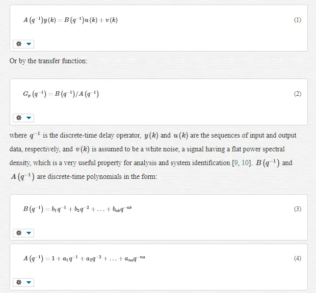
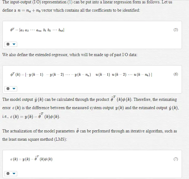
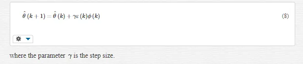
A dynamic system model can be represented in several different ways, particularly in time and frequency domains. When the objective is to obtain a dynamic linear model around an operation point using sampled data, a discrete linear parametric model can be used such as an autoregressive with exogenous inputs (ARX) model. The ARX model can be represented in the discrete time domain by [9, 10]:
PERSISTENCY OF EXCITATION AND DATA ACQUISITION
Before data acquisition, a previous system study is necessary to find the best way to obtain dynamic information of the plant. Analyzing system modes frequencies, an appropriate excitation test signal can be designed, which will excite the plant in a range of desired frequencies. This operation results in a better capture of dynamic information of the system, thus improving the dynamical model estimation.
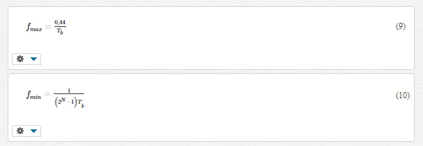 The system to be identified has its dominant modes in a characteristic range of frequencies. Therefore, to excite the plant in an appropriate manner, the input signal must be designed to have an approximate uniform power spectrum in the dominant range. An exciting signal satisfying this property is the pseudo-random binary sequence (PRBS), which is a binary signal that can be generated by using digital techniques [10]. This can be done by using a feedback shift register having a length of N cells and a sample generation interval Tb. From knowledge of the minimum and maximum values fmin and fmax for the desired range of frequency excitation, the values of N and Tb can be calculated by using equations (9) and (10) [9, 10, 11]:
Design of the controller to damp electromechanical oscillations
POLE SHIFTING TECHNIQUE
The damping controller goal is to increase the dominant mode damping, without changing significantly the natural frequency (ωn) of this mode. In order to perform this task, the pole shifting technique was utilized to obtain a controller able to provide a stable closed loop system and performance characteristics as specified in accordance with the designer requirements. This method is a particular case of the general pole placement method.
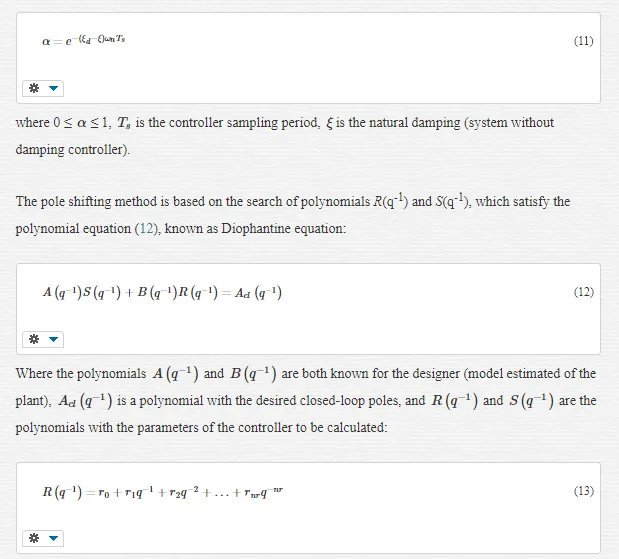
In this technique, the open-loop dominant poles must be radially shifted to a new position toward the origin of the unitary circle in the z-plane. The amount of the radial displacement is specified by a contraction factor α, according to the desired degree of damping for the closed loop system [12, 13]. Therefore, the designer first specifies a desired value, ξdξd, for the damping of the electromechanical mode and then calculates the value of the shifting factor α, by using:
SMITH PREDICTOR
Field tests performed at the diesel power plant revealed that there is a considerable dead time. For the tests described in this work, dead time is the time delay taken for the electric power signal starts to react after the application of a variation on the electro-hydraulic actuator. Smith Predictor is an adequate method to design controllers taking into account the observed delay [13]. The resulting controller with Smith Predictor consists of the digital controller C(q−1)=R(q−1) /S(q−1)Cq-1=Rq-1 /Sq-1 with two additional internal feedback loops (see Figure 8), where one is a linearized estimated model of the plant without considering the time delay Gˆp(q−1)G^pq-1, while the other takes into account the model with the time delay q−dˆGˆp(q−1)q-d^G^pq-1.
Experimental field tests
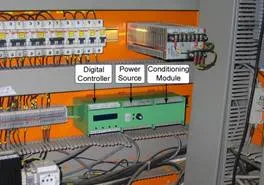
The damping controller was successfully installed and validated by experimental field tests carried out at Santana Power Plant. The controller equipment has been installed in a cabinet of the control system of an 18 MVA diesel generating unit (Figure 9). Tests for model identification and estimation, with subsequent design and test of the proposed damping controller operating in closed-loop have been performed, with results showing an increase of the damping of the dominant electromechanical mode.
ANALYSIS OF THE SYSTEM RESPONSE FOR THE APPLICATION OF A STEP VARIATION
Step response is a useful way for an initial understanding of the system dynamic behavior, revealing some important characteristics that can be used for system modeling. Thus, with the damping controller disabled and the developed equipment programmed to operate only as a step generator, step variations were applied in the command of the fuel valve of the diesel engine. In consequence, the dominant oscillation mode with a frequency around 2.5 Hz, was observed in the electrical power signal. The amplitude of the test signal was configured to 5 mA, which is equivalent to an increase of 5% in the steady state opening of the fuel valve at the operation point considered, while the steady-state valve opening is set at 50 % (9 MW of active power).
These initial tests were also useful to identify possible nonlinearities of the system, such as deadband and time delay. These phenomena are usually found in hydraulic and thermal systems, such as the electro-hydraulic actuator and the diesel engine, and if they are ignored, may be difficult to tune the control system. In order to assess the nonlinearities, a series of tests was performed, which showed that the electro-hydraulic actuator has an excellent sensitivity and a dead zone that does not compromise the system control. So it was not necessary to implement any deadband compensation strategy in the controller. The field tests have shown that the diesel engine actuation system presents a dead time around 400 ms. In order to deal with this observed dead time, a Smith Predictor strategy was applied, as described in Section 5.2 of this chapter.
SYSTEM IDENTIFICATION TESTS
With the goal of obtaining a parametric model for the damping controller design, identification tests were performed in the 18-MVA diesel generating unit without using a damping controller. In order to excite the system electromechanical modes of interest, a PRBS sequence was used, with the parameter Tb equal to 80 ms and N equal to 9, resulting in a minimum frequency of 0.02 Hz and maximum frequency of 5.5 Hz, which excite uniformly the range of possible frequencies of the electromechanical oscillations modes (between 0.2 to 3 Hz) [1, 2]. The point of application of the exciting PRBS signal is the same point used for the application of the step response test, as already described in Section 6.1.
The input and output data sets were collected with a 40 ms sampling period and automatically transmitted to a PC, in which data sets were processed for purposes of identifying models representing the system dynamics in the current operating point. Figures 10a and 10b illustrate, respectively, the data obtained from the plant input variable (current variation in the diesel engine valve admission control) as well as from the plant output variable (power generator active power deviation).
From the acquired data, it is possible to make an estimate of the system response frequency spectrum on the operating point considered. The PRBS spectrum is characterized by being approximately uniform in the range specified by the project (Figure 10c), meaning that all modes between 0.1 and 5 Hz (approximately) were equally excited by the designed test signal. As can be seen in Figure 10d, a 2.5 Hz dominant intra-plant mode, having a small damping, can be observed from the electrical power deviation signal. Therefore, it is advisable to design a damping controller in order to improve the damping of this dominant oscillation mode.
The acquired data was divided into two data sets. The first one was used for the parametric model identification process, while the other set was used for model validating purposes. The identification process was carried out using a non-recursive least squares algorithm [10]. A fourth order ARX model structure was chosen, having 4 parameters in the numerator (B), 4 parameters in the denominator (A) and a discrete-time delay of 10 sampling intervals (400 ms).
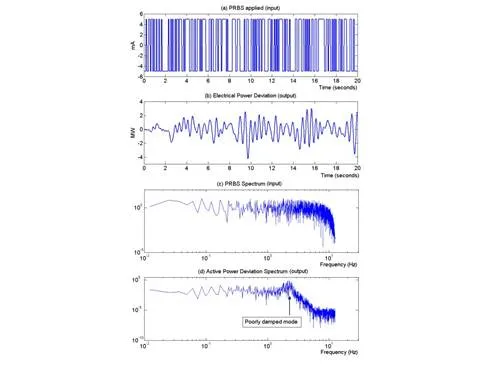
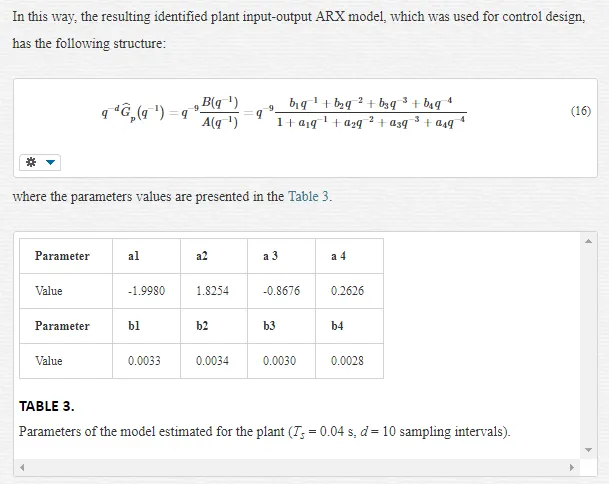
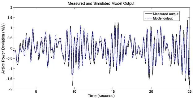
Figure 11 illustrates the comparison between the real output of the system and the output estimated using the fourth order model identified in the tests. The result shows the good estimation of the model parameters. It is also verified that the model successfully captured the oscillatory dynamic of the intra-plant electromechanical mode, observed in field tests performed in the diesel generating unit.
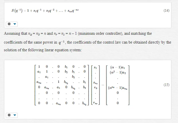
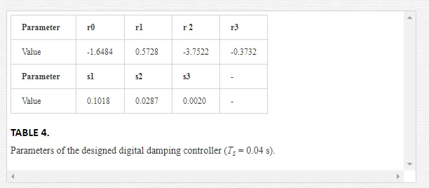
DESIGN OF THE DAMPING CONTROLLER CONTROL LAW
Using the identified model, the damping part of the control law was obtained using the pole shifting method and solving the matrix equation system (15). The controller design main goal is to provide an acceptable damping (in this case, ζd = 0.2), without affecting substantially the electromechanical dominant mode natural frequency and not exciting too much any unmodelled dynamics. In the plant fourth order ARX model (B / A), it is considered only one delay of sampling interval. The additional delay of 9 sampling intervals (d=1+9) is accommodated through the control law scheme implemented using the Smith Predictor, as explained in Section 5. Table 4 shows the parameters of the damping controller used in field tests.
CLOSED-LOOP CONTROL TESTS
After the controller design, its parameters were inserted into the embedded controller. Then the device was programmed to act in the closed loop control mode (damping controller mode), to provide an additional damping signal to the system, through the speed control loop of the diesel generating unit. To evaluate the performance of the damping controller, step type disturbances were applied, as can be observed during the tests illustrated in Figure 12.
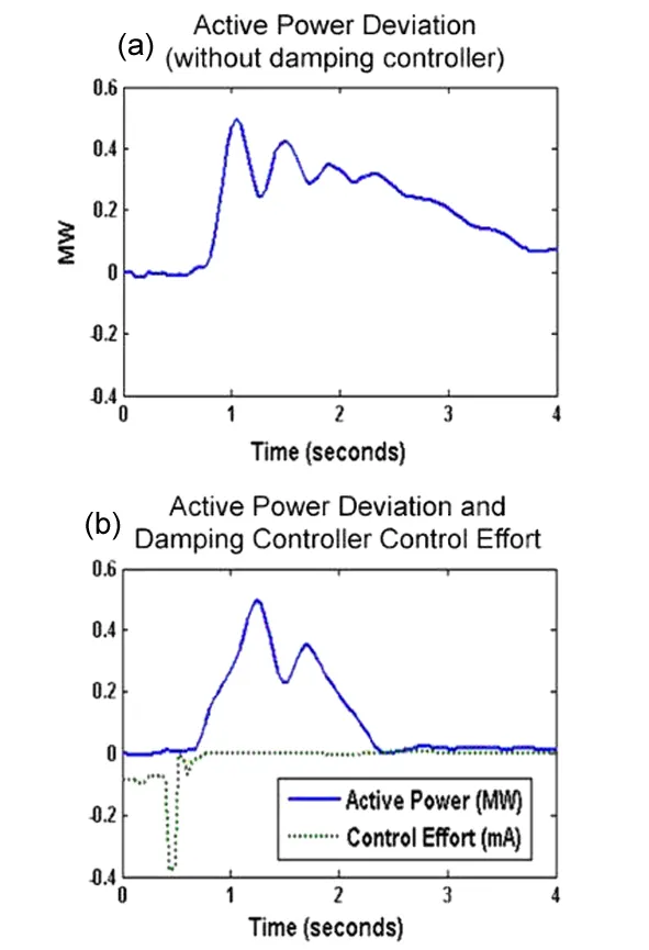
Analyzing the graphics on Figure 13, it can be observed that the inclusion of the damping controller in the speed loop of Wärtsilä considerably improves the stability of the system, making it less oscillatory without affecting the speed governor performance.
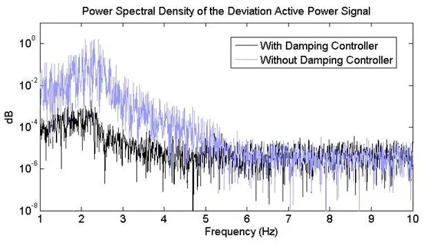
In Figure 13 a comparison between the power spectral density of the active power deviation signal collected with the system with and without damping controller is shown. When the data were collected, the generator was excited by a PRBS signal. It is clear from this measurement that the observed electromechanical mode, around 2.5 Hz, is much more pronounced for the case in which the system operates without damping controller, than when the damping controller is acting on the system.
Conclusion
This chapter presented the design and experimental tests of a digital damping controller which actuates through the speed governor system in order to damp an intra-plant electromechanical oscillation mode. The controller field tests were performed in a real generating unit of 18 MW in the Santana Thermoelectric Power Station.
The actuation of the damping controller through the speed governor was only possible due to the fast response of the diesel engine. Thus, this technology is not recommended for use in systems with machines that have low speed of actuation, as in generating units driven by hydraulic turbines.
Results demonstrated that the system performance was improved after the inclusion of the damping controller, thus increasing the system dynamic stability margins. No adverse interactions have been observed in all performed field tests. This task and others, such as, studies of an adaptive controller design, considering a variable time delay in the loop, will be object of future investigations.