The study of the combustion process in Diesel engines has been going even deeper into depth with the application of new techniques of measure and more rigorous methodologies. This has taken into new expectations in the development of parametric studies and in the construction of tools (physical models or experimental setup) that allow the reproduction of similar thermodynamic conditions to the ones present in the inside of a cylinder in a real thermal engine, making it possible to obtain greater approximations between the theoretical relation and the experimental one.
Experimental setup classification
The physical models or experimental setup used to study the injection-combustion process usually are of very specific characteristics, depending on the phenomena to analyse. These models can be classified in the three following groups:
According to the type of the working fluid
-Models with cold working fluid are used to study sprays in non-evaporating conditions, but many times in conditions similar to the existing ones in a real thermal engine.
– Models with hot working fluid, this kind of model is the best way to study sprays in evaporating conditions and in the majority of times it’s possible to simulate a real thermal engine in its temperature and density conditions.
According to the atmosphere type
-Models with inert atmosphere are used to study diesel spray without the presence of flame. Its greater application is basically the biphasic study of the spray (liquid and vapour).
-Models with reactive atmosphere, this kind of model is generally applicable to combustion studies and normally atmospheric air is used to achieve the reaction.
According to the geometry of the chamber
Models of constant volume vessel are used to study the diesel sprays in non reactive atmosphere and reactive atmosphere. This kind of model is not of common use, most of all on the development of studies of the sprays by means of reactive atmospheres since they require previous ignitions of mixtures of combustible gases to achieve high pressures and temperatures in the inside of the injection chamber.
Historically the first developed studies about combustion process in a thermal engine were by means of direct recording of the luminosity of the flame, and afterwards by the Schieren technique for studies of auto-ignition and the knocking combustion. The visualization involves the formation of visible images directly or indirectly by the action of light over sensible materials to the latter. Therefore the light and the recording of the formed images are essential to any form of visualization. The light can be generated by the object itself if it’s luminous (auto-ignition or combustion). If it’s not, the light source has to be deployed to illuminate the object to reflect (free injection). Traditionally the photographic films were the only way to register images for the chemical processes induced by the action of light, however in some applications; the photoelectric devices are now substituting the photographic film. Due to the nature of the engines combustions, each image must be taken in a very short amount of time to freeze any fluid movement or of the flame during the exposure. This can be obtained by intermittent recording with high speeds of the shutter to register an image from a cycle, and a sequence of images in function of the turning angle of the crankshaft along many engine cycles or by means of the recording of hundreds of images per second to obtain a image sequence within the same engine cycle (relating to the first recording case as a projection of a high speed monostable image, and the last one as high speed continuous, correspondingly). These recording methods and other techniques of measure have been evolving gradually and increasing their application to the different kinds of existing models, such as it will be mentioned in the subsequent sections.
The analysis of diesel sprays has had very important advancements beginning with the physical model implementation because during time, very specific studies have been developed. In the last decade of the 20th century, (Hiroyasu et al., 1989) was one of the pioneers in the use of injection models and in the implementation of visualization methods (Fraunhofer diffraction). Hiroyasu, in his investigations to study Sauter’s medium diameter (SMD), used an injection model with the only possibility of doing experiments under low atmospheric conditions (pressures of the order of 3 bar and temperature of 285 K), which allowed relatively good microscopic studies to be made but with limitations to study the diesel spray under the thermodynamic variables that can be achieves in a real thermal engine.
To develop his experiment of SMD, (Minami et al., 1990) used a similar model to that one employed by (Hiroyasu et al., 1989), where the objective was to obtain the density conditions similar to the existing ones inside the combustion chamber of a real thermal engine. This author to develop his experiments used as the working fluid pressurized nitrogen at 20 bar and the injection pressures analysed were of the order of 2000 bar. These pressures could not be analysed using the model of Hiroyasu due to the low densities that were achieved in his model, so that it resulted irrelevant to do certain kinds of studies, mostly in high injection pressures. Minami employed the Fraunhofer technique to visualize
the diameter of the droplets, using a lighting source based in a ruby laser beam pulsed at 30 ns and with a wavelength of 694 nm. Unlike Hiroyasu, Minami expanded the beam making it parallel to the spray through lenses, which afterwards is attenuated by the own fuel spray, where the transmission of light is focused by a parabolic mirror with which an image of the filmed spray on the 35 mm film is obtained. It was possible in this model to analyse the penetration of the spray by installing a high speed photographic camera to take the images and replacing the beam of light by halogen lamp as the light source.
There where basically two problems to clear up the interference of stripes in the photographic plane when using this technique:
– The first issue was due to the interferences caused by the thickness of the visualization window which was approximately 50 mm. This problem was solved by changing the trajectory of the beam between the reference and the object, using a intensity rate of 9:1 and fixing the point that focuses the lens of the relay as close as possible to the photographic plate.
– The second problem was generated by the collision of waves, which were produced in the interior of the chamber in a short amount of time during the period of injection. This was a consequence of the fuel injection velocity that surpassed the sound velocity. The collision of waves inside the combustion chamber made it difficult to take pictures because of the reflection inside it. The problem was solved by changing the time of synchronization of the injection time in reference to the picture taking, changing to times of 0,2 to 0,4 ms after start of injection.
The evaporated diesel spray studied by (Tabata et al., 1991) was made using a model similar to that presented by others scientist (Hiroyasu et al., 1989) and (Minami et al., 1990), with a small difference in its configuration. A heat system was installed in the interior of the chamber which had the objective of heating up the working fluid (nitrogen) to conditions that were optimal to achieve fuel evaporation. The main drawback studying evaporated diesel spray was the low range of available densities for high permissible temperatures. Due to this inconvenience it was impossible to reproduce similar thermodynamic conditions to those found in a thermal engine. It was limited to predict behaviours at low pressures (pressures inside the injection chamber in the order of 20 bar). (Higgins et al., 2000) studied the ignition of the spray and the behaviour of the pre-mixture of burn in a model of constant volume, where it was possible to achieve pressures inside the chamber of 350 bar and a temperature range of 800 K to 1100 K for densities between 7.27 kg/m3 y 45 kg/m3. This model, unlike those used by other authors (Hiroyasu et al., 1989), (Minami et al., 1990) and (Tabata et al., 1991) has two spark plugs and a ventilator to equalize the atmospheric conditions in the inside of the chamber, besides of having the walls electrically conditioned to simulate the conditions of the wall temperature found in a thermal engine. Another objective for this conditioner was to avoid the vapours of the fuel to condensate on the visualization windows. This model didn’t require any kind of modifications to develop burning or free injection studies, unlike the one used by (Minami et al., 1990), which did need very sophisticated adaptations to be able to make more complex studies, as the burning study.
The effects on the diesel spray caused by the geometry of the chamber were studied by (Montajir et al., 2000). To develop the investigations they based themselves on an experimental installation which consisted in a small thermal engine of slow speed regime and with a combustion head of rectangular geometry adapted with a window for visualization. In this model as in the ones described previously, nitrogen was used as the working fluid (injected in the cylinder a temperature of 293 K and with a pressure inside the chamber of 45 bar) to visualize the diesel spray without combustion. To achieve the development of studies in different thermodynamic scopes with this model, the main option was to change the compression ratio. This was achieved by placing spacer rings between the cylinder and the combustion head. This modification used to be also very complex and expensive. Furthermore it didn’t allow continuity in the experimental session because of the constant stops required to carry out mechanical changes in the installation.
The stratification effects of the combustion were studied by (Plackmann et al., 1998) using a model of constant volume, also called combustion constant volume vessel. Where the visualization took place through three quartz windows. One of the windows was located in the back side and the other two in the middle section of the pump. This model was pressurized with an air-propane mixture with pressures of 40 bar; these fluids were used as oxidant and test combustible respectively. The ignition took place by the means of two diametrically opposite electrodes which function as a spark plug to provoke the spark. One of the electrodes was connected to a high tension source that came from a discharge capacitive ignition system and the other one to mass, being this last system to be the one that caused the difference in electric potential to achieve the ignition of the mixture.
In their studies about the behaviour of gasoline direct injection (GDI), (Shelby et al., 1998) used an engine with three optical accesses made out of quartz. To carry out the visualization of burning the planar laser induced fluorescence (PLIF) as the technique of measure and a high speed camera to film the combustion process were used. The camera was placed perpendicularly to the beam, having with this the advantage of taking images directly. This thermal engine unlike the one used by (Montjair et al., 2000) had completely transparent walls, which allowed a complete capture of the phenomena (injection-combustion). Furthermore, it required complex routines at the moment of doing any changes in the installations configuration.
With the purpose of visualizing the atomization process in a gasoline direct injection system, (Preussner et al., 1998) used a model pressurized with oxygen (pressure and temperature of 20 bar and 673 K correspondingly). Where the combustion products of each cycle were constantly evacuated by the use of nitrogen and the visualization of the atomization process was done through windows located on the far ends of the injection chamber. Mie-Scattering was the technique of measure used during the experiments. In addition to this technique, the scientists developed tests with the laser induced fluorescence technique, which proved not to be the most appropriate for some measures in the gasoline direct injection systems, because it is an optical method of measure somewhat incoherent to detect concentration of species compared to Mie-Scattering. However, it was possible to use other techniques of measure. One disadvantage presented by this model was the way of evacuating the burn gases, because it was required to introduce nitrogen to the injection
chamber when the cycle ended to expel these gases and was not recoverable, which made expensive the experimentation, besides of needing very long test routines because of discontinuity in the tests due to the type of cleaning used.
In his experiments to study the effects of vaporization, (Takagi et al., 1998) used an experimental installation based on a thermal engine of 2.0 litres provided with sapphire walls and only one optic access for image capturing. The optic access was placed in one section of the piston head, being the most appropriate collation place due to the geometric characteristics of the model. In the same way as Preussner, laser induced fluorescence was used as the technique of measure, obtaining extremely satisfying results in addition to confirm (Preussner et al., 1998) theories, who postulated that the laser induced fluorescence technique was no the best option to study the combustion effects due to the problems generated to detect species. Something that does not exist in the case of vapour concentration studies, as long as the fuel is mixed with tracers to make it behave as a fluorescent source (the combustible by its own nature tends to illuminate when its subject to high pressure and temperature, which is why tracers are required to carry out concentration studies, because the presence of tracers allows to define the different wavelengths for each element that constitutes the mixture). This model wasn’t sufficiently flexible enough for the use of other techniques of measure due to the fact that the sampling process of images was of the intrusive kind, therefore making it an inappropriate method for the study of internal processes in an internal combustion engine.
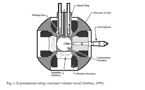
To study the effects of the injection pressure and the diameter of the nozzle on the fumes emissions, (Siebers & Pickett, 2002) used a model consisting in a chamber of constant volume where it is possible to simulate similar thermodynamic conditions to the one in a Diesel engine (Figure 1). Other applications for this model are described in (Naber & Siebers, 1996), (Siebers, 1998), (Siebers & Higgins, 2001) and (Siebers et al., 2002). The chamber has four optic accesses placed orthogonally and equidistant, having the advantage of using different optical techniques simultaneously making more than one analysis in each experiment. But it also has disadvantages, mainly the way of obtaining the appropriate thermodynamic conditions in the chamber’s interior. These conditions such as the temperature and density are achieved by causing the ignition (by means of a spark plug) of the combustible gases in the inside of the chamber, the method is unusual and in many cases even dangerous. The range of operation for the temperature as for the density is in the order of (600 a 1400) K and (3,6 a 60) kg/m3 respectively. Furthermore, it’s possible to regulate the concentration of oxygen in the interior of the chamber from cero (e.g., for inert conditions) to values greater than 21% in volume, depending on the type of study aiming for.
Proposal of the physical model
To achieve the optimal feasibility the physical model must always obey the following equivalence requirements:
-Reproduce inside the injection chamber, the thermodynamic properties that the working fluid has in a real thermal engine in normal operation.
-Easiness to sweep the atomized fuel in the injection chamber and maintain the visualization accesses clean.
-To make possible the studying of different phenomena it’s indispensable to have versatility in the cases of the density magnitudes and in the working fluids thermodynamic properties, besides having flexibility in the geometry of the injection chamber (the geometry of the injection chamber can vary with small arrangements or by making modification of the supplementary type in the physical model).
– Allow repetitiveness in the tests when constant thermodynamic are maintained.
Operational Conditions
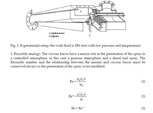
The operational conditions depend fundamentally on the characteristics of the working fluid in the injection chamber at the moment when the injection of fuel is initiated. These conditions commonly vary from one engine to another. When a physical model is designed, where the thermodynamic properties of the working fluid are not similar to those of atmospheric air, (generally heavy molecular gases are used) the model must be reproduced
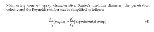
based on analogies, an equivalent atmosphere to that in a real thermal engine in low pressure and temperature conditions and these must be easily achieved, so that the development of the experimental study is allowed (Figure 2). It is to be noted that model of hot fluid that will be presented in the next sections doesn’t need analogical processes because this physical model is in fact a real thermal engine. However, the thermodynamic variables that are desired to combine for each particular study must be correctly defined. On the one hand, it’s a safety routine and on the other hand, it gives knowledge of the high pressure range that can be achieved in the combustion chamber. This last argument is fundamental for the defining of the thermodynamic conditions inside the cylinder (Arrègle,
1998).
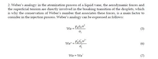
The results can be directly used as long as Sauter’s medium diameter and the injection velocity are kept, which implies the equality of analogies. It can be considered that during a very short amount of time of the atomization, the heat transfer between the working fluid and the fuel in the combustion chamber is low. The fuel starts to heat up when it is found as a droplet. Therefore, if a same fuel is used the superficial tension variation that occurs between the real thermal engine and the physical model will be very small. This hypothesis is confirmed by the results obtained by (Hiroyasu & Arai, 1990), in which differences during the atomization process at temperatures of the working fluid between 293 K and 573 K aren’t seen. This is why Weber’s analogy is simplified to a density conservation of the working fuel between the real thermal engine and the physical model.
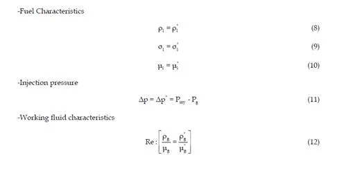
3. Analogy equality: the equality of analogies between Weber and Reynolds is simplified as shown. This analogy between the real thermal engine and the physical model is in accordance to the theoretical and experimental results on atomization and spray penetration. These results are presented by the authors previously cited.
Geometric characteristics of the physical model
The geometric characteristics of the physical model must obey certain requirements. The most important one is in the injection fuel chamber, which must have optical accessibility to make proper measurements and observations. As it has been previously explained, to carry out the majority of experiments more than one technique of measure is required. This is why it is convenient to have several optic accesses (these access are generally windows, mainly out of quartz). The geometry of these accesses is in function of the test aimed to do, being in the majority of cases the front longitude of the spray the basis of study. In a real thermal engine the diesel spray length is conditioned by the diameter of the combustion pre- chamber (in a thermal engine of indirect injection) or by the piston bowl (in the case of thermal engines of direct injection). This length in a diesel spray of an internal combustion engine of self-propulsion can measure between 18 to 50 mm before the collision with the wall. However, in the majority of cases the sprays manages to collide with the wall of the bowl before the atomization process has ended. It’s because of this reason the importance of studying the spray up to lengths in the order of 100 mm, sufficiently long for the spray to achieve complete atomization, having special attention to the injection chamber. A second requirement that the physical model’s geometry must fulfil is the easiness of evacuation of the injected fuel inside the injection chamber to reduce the dirtiness of the optic accesses. Many scientists as seen in the previous section (Hiroyasu & Arai, 1990), (Hiroyasu et al.,
1989) and (Minami et al., 1990) have used chambers of the volumetric type were the atmosphere is renewed after every injection. In using this methodology of measure, an injection system is required that allows having certain flexibility to inject discontinuously and making possible the admission of clean fluid before each injection cycle. This system usually doesn’t allow the use of many optical techniques because in very particular cases, it’s necessary the use of tenths of injection cycles to do a complete spray study, having very long, arduous and costly test sequences.
In this section the development, designed and tune-up of an experimental installation is presented. The main objective is to carry out studies of the evaporated diesel spray in inert and reactive conditions. To achieve this purpose a model has been brought up based on a two stroke thermal engine and a group of auxiliary equipment that allow the adjustment of operational parameters of the installations and of control for the various independent variables that interact in the injection-combustion process.
Objectives of the experimental installation
-Simulate the process of direct injection of diesel fuel in high pressure, density and temperature conditions.
-Study the microscopic and macroscopic characteristics of the diesel spray in evaporative conditions.
-Carry out experiments of the diesel spray in an inert and reactive atmosphere.
Design requirements and determining factors
The experimental installation systems must allow the following functions and capacities:
1. Control and regulate the working fluid’s temperature and pressure.
2. Optic accesses to visualize the diesel spray by means of visualization techniques.
3. Modification of characteristic parameters of the injection.
4. The injection chamber must have a minimum number of movements in relation to the visualization equipment.
Observations relative to system design
The most relevant aspects that must be considered in the design of the main systems that constitute the experimental installation based on a thermal engine are described next:
1. To be able to have high pressures and temperatures of the working fluid in the admission system.
2. Having a good regulation of the exhaust backpressure.
3. The thermal engine must be thermally fitted by an external system that allows it to have optimum operational conditions.
4. There must be an injection system for high pressure independent of the thermal engine.
5. The vibration control to reduce vibrations transmitted by the thermal engine to its surroundings must be controlled by a limitation vibration system.
The experimental installation allows switching between two different configurations to study the diesel spray in evaporative conditions. These configurations are detailed as follows:
1. Open loop configuration, reactive atmosphere: this configuration allows studying the diesel spray injection in an oxidant atmosphere. The working fluid used to fill the control volume where the fuel is injected is atmospheric air. When the combustion is executed, the gases and the product species of the latter are then evacuated to the atmosphere after each operational cycle. Afterwards, fresh air is introduced in the cylinder to carry out a new injection.
2. Closed loop configuration, inert atmosphere: This configuration allows studying the diesel spray in an inert atmosphere in which there’s no oxidation of the injected fuel. To achieve this, a nitrogen supply system has been incorporated to the installation with which the injection chamber is filled.
Experimental installation characteristics
-Repetitiveness of the various tests so an excellent stability in the different operation points is achieved.
-The precision in the measures demands quality of the measuring equipment and an accurate calibration of them to avoid systematic errors during the tests.
-Having reliability and safety assumes a rigorous fitting of the room where the experimental installation is housed.
-Good accessibility and compatibility to facilitate the control, verification and proceeding tasks on all the thermal engine systems.
Reactive atmosphere configuration
The reactive atmosphere configuration or open loop is useful for carrying out studies of the injection, self-ignition and combustion processes, in the same way to carry out analysis in the combustion process and measures of contaminant emissions. Figure 3 shows the schematic diagram of the experimental installation that is used in the study of diesel sprays in a reactive atmosphere (Martínez et al., 2007) and (Bermúdez et al., 2000, 2003).
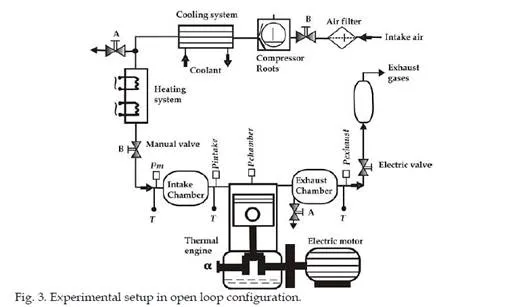
Description of the elements that constitute the experimental installation, impurity filter: A commercial filter is used to purify air from the impurities of the environment:
-Compressor: A Roots compressor is used to boost air from the environment towards the engine’s admission, as well to achieve the sweep of gases produced by the combustion.
-Heat exchanger: it is of the armour and pipe type (water-air). Its function is to regulate the exit air temperature.
-Heater: prepares the air of admission through a resistance heater which is installed in series with the water-air exchanger.
-Pm: the medium pressure sensor absolute scale is in charge of sending a voltage signal to the PID controller so it can regulate the opening of the electro valve. The aperture of the electro valve is in function of the target pressure established in the admission.
-Pintake: is the instantaneous pressure sensor in absolute scale that measures the pressure in the admission chamber, which is used as a reference for the medium pressure in the cylinder.
-Pexhaust: is the instantaneous pressure sensor in absolute scale that measures the pressure in the exhaust chamber. This pressure measurement is used as an operating reference for the exhaust backpressure electro valve.
-T: are the thermocouples type k: the thermocouple is located downstream of the admission chamber and is responsible of measuring the air’s temperature just at the entrance of the admission chamber. This signal is sent to a PID that rules over the heater based on the established target temperature. The thermocouple is located upstream from the admission chamber and measures the temperature just before it enters the admission.
-Electro valve: to increment the pressure of the working fluid in the injection chamber it’s necessary to establish a backpressure in the exhaust to avoid a short cut of the working fluid from admission to exhaust. This is achieved by closing the exhaust systems electro valve.
-A: represents the valves used to drain the vapour from the circuit, as of residual fuel as well of the oil that accumulates on the ducts.
-B: represents the sphere valves used to free the circuit elements. These are mainly used when the installation operates with inert atmosphere.
Inert atmosphere configuration
The inert atmosphere configuration or closed loop is used for carrying out studies of the injection process in liquid phase as well as in vapour phase. This configuration allows the spray to evolve through the combustion chamber presenting the two phases (liquid and vapour) without permitting flame during the process. This is achieved by a very simple way, the spray is injected in a control volume (combustion chamber) were the working fluid is a inert gas (e.g. nitrogen), therefore a volume free of oxygen molecules but with similar properties to those of air.
Figure 4 shows the schematic diagram of the experimental installation used to study diesel sprays in an inert atmosphere.
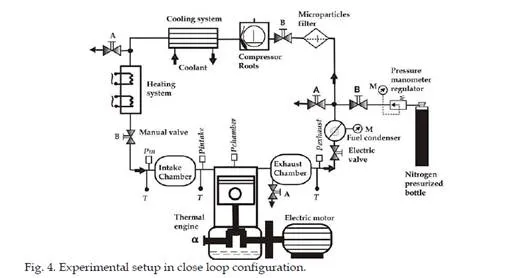
Description if the elements that constitute the experimental installation. All of the elements that constitute the adapted experimental installation to study diesel sprays in a reactive atmosphere are used in inert atmosphere, with the exception of the expansion chamber and the filter of particles. Additionally to these, two elements which are indispensable for this configuration are included. These elements are described next:
-Condensate separator of the collision type: the configuration in a closed loop must have nitrogen recirculation without the presence of fuel, therefore the injected fuel in the combustion chamber and the gas in which the latter has been injected to, must be separated once they have been expelled from the cylinder. The condensate separator is in charge of the first phase of separation. Upon circulating the mixture (fuel-gas) through the discharge system and arriving at the separator, where the fuel is then condensed into small drops that go to the bottom of the vessel and the gas and other particles that are still mixed are separated by a filter f micro particles (see next section). The liquid fuel concentrated at the bottom of the vessel is purged by a system of volumetric valves and disposed thereafter.
-Filter of micro particles: the second phase of gas purification is carried out through a filtering of high purity that allows the gas to be separated from possible fuel residues that haven’t condensate in the previous phase, or from possible solid particles dragged from the circulation system or other particles loosed by the engine. The filter of micro particles allows the separation of particles up to 0.001 µm.
Operation mode
The complexity of operation and precision of the measures is of the same magnitude as on the reactive atmosphere configuration and also the mechanism for the circulation of the working fluid. When the installation is operating in an inert atmosphere, the nitrogen is boosted by the Roots compressor through the conditioner system and afterwards introduced
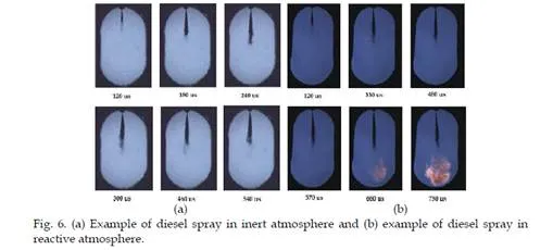
into the cylinder. After the fuel is injected and mixed with gas, this mixture (fuel-nitrogen) is expelled towards the condensate separator system and to the high efficient filter, where the larger drops of fuel are first condensed and then the solid particles dragged by the gas through the circuit elements or the engine are eliminated. Once the nitrogen has been purified, it is driven up to the Roots compressor admission where it is boosted again towards the motor to carry out a new injection cycle. A pressurised nitrogen deposit is used to fill up the close loop circuit before initiating operations of the installation. Once the installation is operating, the deposit with help of an electro valve and a PID regulator are responsible of maintaining a constant volume of nitrogen circulating through the system since some small gas leaks towards the engines crankcase through the looseness between the piston and the cylinder may exist. The Figure 5 (a) shows a schematic diagram of the combustion chamber through which is possible to visualize the injection-combustion process. Figure 5 (b) shows an example of an image sequence of a multiple spray. Figure 6 (a) and (b) show a sequence of the development of an axi-symetric spray in an inert and reactive atmosphere respectively.

Conclusions and remarks
In this chapter, several experimental setup based on different models have been presented. This experimental setup allows a basic study of the injection and combustion processes. The models have diverse applications and their use depends on the kind of study that is intend to carry out, these models are limited in some aspects, chiefly in the work fluid renewal, likewise is used to being complicated to reproduce the thermodynamic conditions that are presented in the combustion chamber of a real thermal engine. The experimental setup that is presented and based on a thermal engine is a excellent tool that permits to reproduce thermodynamic conditions and of operation as the existing in a engine in standard conditions. The cylinder head that has arranged the engine has three optical accesses which is allow visualization and the use of optical techniques. Diverse techniques have been utilized in this experimental setup; like LDA, PDA, PLIEF, PIV, Spectroscopy, Raman and Rayleigh Scattering, Two colors, and Shadowgraph, principally. These studies have permit to characterize the diesel spray in evaporating conditions to obtain relevant information that permit to improve the combustion processes in modern diesel engines.