Numerous papers have indicated that the present standard systems of injecting fuel directly into the combustion chamber, in the most economical, direct-injection diesel engines, have reached the limits of development. In order to maintain the emission of toxic components of exhaust gases within the ranges defined by both EURO V and projected EURO VI standards, various modifications to the combustion system will be necessary. It is known that injection through a conventional multi-hole nozzle, in combination with induced swirl in the air in the chamber, does not ensure that particulates and oxides of nitrogen are not formed. These toxic components are among the most difficult to subsequently remove from the exhaust gases (Hiroyasu & Arai, 1990; Peake, 1997; Kuszewski & Lejda, 2009). Effective limitation of NOX and PM emission can be achieved by providing proper macro structure parameters of the spray. First of all, it is very important to distribute fuel effectively in the combustion chamber, considering the rotary motion of the air and the spray shape (Beck et al., 1988; Dürnholz & Krüger, 1997; Kollmann & Bargende, 1997). Next, a larger range of the spray front and apex angle of spray is needed (Kollmann & Bargende, 1997; Kuszewski & Lejda,
2009). Moreover, it is important to know the distribution of fuel in the spray, because then it is possible to select the correct rotary motion of the charge in the cylinder, which will guarantee as effective a mix of the air and the fuel as is possible. A fuel spray with a different macro structure might have an important effect on these processes; however it is necessary to use a different type of injector, a new type of construction and modus operandum (Varde and Popa, 1983; Kuszewski, 2002). The design for such a device forms the subject of this paper (Metz & Seika, 1998; Szlachta & Kuszewski, 2002; Szymański & Zabłocki, 1992). The special feature of the spray nozzle of this injector is the variability of the fuel-spraying holes during injection. The variability of the cross-sections of these holes is achieved by the rotary swinging movement of the needle (RSN injector). The results of investigations described below show that a spray generated by this injector design has macro-structural parameters that differ from those of a standard traditional injector.
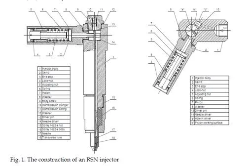
The construction and principle of operation of an injector with rotary swinging needle movement
The construction of an injector with a rotary swinging needle movement is shown in Fig. 1. Fuel is supplied through a high-pressure tube to the upper part of the injector body. The fuel pressure acts on the working area ‘b’ of a piston, 7, joined by a pin, 13, to an injector needle driver, 14. This causes the driver to rotate simultaneously with the rotation of the needle, 17, which is joined to the driver.
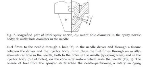
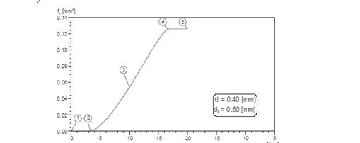
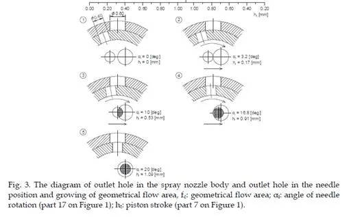
![]() movement-causes a misalignment of the spray and the outlet holes, so that they are momentarily occluded, resulting in a non-circular area of flow (Fig. 3). This area increases in proportion to the increasing angle of needle rotation. It should be mentioned that during the initial phase (low rotary angle), the needle has a ‘dead’ movement, which prevents increase of the flow area. The rotation of the needle in one direction continues so long as the axes of the spraying and outlet holes overlap. In this position, the piston of the driver rests on the end stop, 3, which acts as a regulatory element, limiting needle movement. The release of fuel causes a decrease in fuel pressure, which causes the spring, 6, to move the piston, 7 (moving in the servo, 2), screwed into the injector body, until it reaches a position corresponding to the closure of the injector. During this movement the flow area from the injector decreases to zero. The unique feature which distinguishes the new construction from the standard construction is that fuel flows out through a non-circular area, quasi- lenticular in shape, during the beginning and end phases of injection. During injection, fuel is throttled only in this non-circular area.
movement-causes a misalignment of the spray and the outlet holes, so that they are momentarily occluded, resulting in a non-circular area of flow (Fig. 3). This area increases in proportion to the increasing angle of needle rotation. It should be mentioned that during the initial phase (low rotary angle), the needle has a ‘dead’ movement, which prevents increase of the flow area. The rotation of the needle in one direction continues so long as the axes of the spraying and outlet holes overlap. In this position, the piston of the driver rests on the end stop, 3, which acts as a regulatory element, limiting needle movement. The release of fuel causes a decrease in fuel pressure, which causes the spring, 6, to move the piston, 7 (moving in the servo, 2), screwed into the injector body, until it reaches a position corresponding to the closure of the injector. During this movement the flow area from the injector decreases to zero. The unique feature which distinguishes the new construction from the standard construction is that fuel flows out through a non-circular area, quasi- lenticular in shape, during the beginning and end phases of injection. During injection, fuel is throttled only in this non-circular area.
Method of investigations
The parameters of the macrostructure of the stream of sprayed fuel were determined on the basis of measurements carried out using specially constructed equipment, which enabled both the direct observation of the development of the spray during the fuel injection to a chamber of fixed volume (Metz & Seika, 1998; Szlachta & Kuszewski, 2002; Szymański & Zabłocki, 1992) and the measurement of the fuel distribution within the spray of droplets. The scheme of test stand for visual studies is shown in Fig. 4.
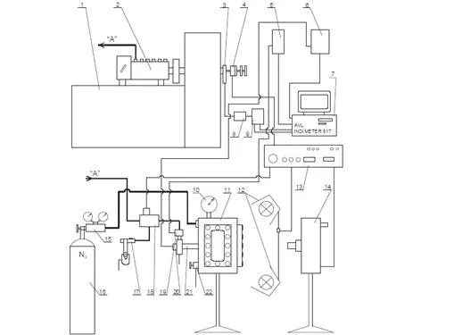
Fig. 4. Scheme of test stand for visual studies, 1: test bench Hansmann EFH 5008; 2: injection pump P56-01; 3: position and rotational speed sensor of pump shaft AVL; 4: synchronizing plates; 5: charge amplifiers AVL 3056; 6: tensometric bridge; 7: computer with data acquisition device for high-speed courses recording AVL Indimeter 617; 8: signals decoder;
9: feeder; 10: manometer; 11: visualization chamber of constant volume; 12: lights; 13: driver of high-speed camera; 14: high-speed camera; 15: pressure regulator with manometers; 16: nitrogen cylinder; 17: auxiliary injector; 18: switching valve; 19: piezoquartz pressure sensor AVL 5QP6002; 20: inductive position sensor of injector piston (or needle); 21: tested injector;
22: release valve
The essential elements of test stand were: visualization chamber of constant volume, where a fuel was injected by using tested injector, 21, test bench ,1, injection pump, 2, for pumping the fuel to injector, the high-speed camera, 14, with driver, 13, and the computer with data
![]()
![]() acquisition devices for high-speed courses recording 7. Inside the chamber to which fuel was injected, there was fixed backpressure verified with manometer, 10. For safety reasons, gas filling the chamber was nitrogen, passed from the cylinder 16. The fuel for tested injector, 21, was supplied from the injection pump, 2, driven by an electric motor of test bench, 1. Switching valve, 18, referred fuel from injection pump to the tested injector, 21, (at the time of visualization test of stream development) or to the auxiliary injector, 17, (in the intervals between fundamental tests). To record of fuel stream images, it was necessary to synchronize the work of high-speed camera, 14, the test bench, 1, the lights, 12, and switching valve, 18. It was obtained using a special camera driver, 13, co-operating with synchronizing plates, 4, fixed to the driving shaft of the test bench engine. Additionally, during work of the high-speed camera, using piezoquartz pressure sensor, 19, the values of pressure before the injector were recorded. Furthermore, using inductive position sensor, 20, it was recorded displacement of injector needle (or a piston in the injector of new type) and using an optical rotation speed sensor, 3, – it was recorded rotational speed of injection pump camshaft. The record of these parameters was possible thanks to the computer, 7, with a special data acquisition device. The stream images were recorded at a speed of 5000 fps. The successive images of a developing fuel stream were recorded every 0.0002 s (0.2 ms). Next, the films of width 16 mm were scanning and digital images were analyzed using a computer.
acquisition devices for high-speed courses recording 7. Inside the chamber to which fuel was injected, there was fixed backpressure verified with manometer, 10. For safety reasons, gas filling the chamber was nitrogen, passed from the cylinder 16. The fuel for tested injector, 21, was supplied from the injection pump, 2, driven by an electric motor of test bench, 1. Switching valve, 18, referred fuel from injection pump to the tested injector, 21, (at the time of visualization test of stream development) or to the auxiliary injector, 17, (in the intervals between fundamental tests). To record of fuel stream images, it was necessary to synchronize the work of high-speed camera, 14, the test bench, 1, the lights, 12, and switching valve, 18. It was obtained using a special camera driver, 13, co-operating with synchronizing plates, 4, fixed to the driving shaft of the test bench engine. Additionally, during work of the high-speed camera, using piezoquartz pressure sensor, 19, the values of pressure before the injector were recorded. Furthermore, using inductive position sensor, 20, it was recorded displacement of injector needle (or a piston in the injector of new type) and using an optical rotation speed sensor, 3, – it was recorded rotational speed of injection pump camshaft. The record of these parameters was possible thanks to the computer, 7, with a special data acquisition device. The stream images were recorded at a speed of 5000 fps. The successive images of a developing fuel stream were recorded every 0.0002 s (0.2 ms). Next, the films of width 16 mm were scanning and digital images were analyzed using a computer.
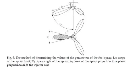
The visual studies enabled the following to be analysed: the range of the spray front – LC, the apex angle of the spray – ΘS, and the area of the spray projection in a plane perpendicular to the injector axis – AS. The last criterion of the spray macrostructure estimation was introduced because of the irregular shape of the spray generated by the RSN injector. The method of determination of the values of the analysed parameters of the spray of injected fuel is depicted in Fig. 5. A standard injector with a D1LMK 140/M2 pattern sprayer, and the new RSN injector were compared. Both sprayers had three outlet holes, the diameter of the holes in the standard injector body and the RSN type being equal

Fig. 6. Pictures of fuel spray propagation obtained at use three-hole spray nozzle with rotary
swinging needle movement and standard (po = 170 bar, pb = 20 bar, q = 130 mm3/injection, np = 600 rpm, fuel: DF, 70% RO + 30% DF, RO), dk: outlet hole diameter in the spray nozzle body; di: outlet hole diameter in the needle; ν: kinematic viscosity; DF: diesel fuel; RO: rape oil
In Fig. 6 the pictures of fuel spray propagation obtained at use three-hole spray nozzle with rotary swinging needle movement and standard are shown. From the figure 6 it is clear that the spray generated by injector with rotary swinging movement of the needle is developing in a different way than in the standard nozzle. It causes differences in values of used parameters to assess the macrostructure of fuel spray. In particular it is clear, that the spray forming by injector with a rotary swinging needle movement is irregular in shape, and its area (area of the spray projection in a plane perpendicular to the injector axis), the apex angle of the spray and the front range are usually significantly higher compared to the classical sprayer. Particularly noteworthy are the results presented in Figure 6 concerning rape oil, which is characterized by a high value of kinematic viscosity (ν = 72.5 mm2/s). As we can see, the area occupied by rape oil spray from the RSN needle movement is much larger than achieved for classical sprayer.
The range of the spray front
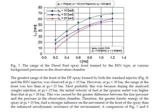
In both injectors the following values were set, being the same for each type: line pressure at the opening of the sprayer po = 170 bar, fuel dose q = 130 mm3/injection and rotary velocity of the camshaft of the injection pump np = 600 rpm. Fuels of different viscosity (Diesel Fuel (DF), Rape Oil (RO), and 70/30 RO/DF mixture), were injected into the observation chamber, which was filled with nitrogen at pressures of 15, 20, and 25 bar. During all investigations of the range of the spray front, the apex angle and surface area of the spray, a time scale of 0–1.4 ms was chosen. Beyond this range, for some injection parameters, the spray front reached the walls of the observation chamber. The range of the spray front for DF, formed by the RSN sprayer under various values of the background pressure in the observation chamber, is presented in Fig. 7. For RSN injector, it can be seen that an increase of nitrogen pressure in the observation chamber caused – as was expected – a reduction in the range of the spray front. This phenomenon is characteristic of standard sprayers, and may be ascribed to the effect of the aerodynamic resistance on droplets of variable size. An increase in the background pressure (gas density), causes an increase in aerodynamic resistance, and reduced dynamic pressure of the gas into which the injection is made, creating adverse conditions for the disintegration of secondary droplets. Therefore, larger droplets with greater penetrative capability are formed (obviously a larger droplet has greater kinetic energy and will therefore travel further).
Radial distribution of fuel in spray drops generated by standard and RSN injectors
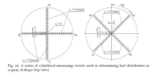
Investigations of fuel distribution were carried out using both injectors in a spray of droplets, at a constant injection pump speed of np = 600 rpm. The fuel dose was adjusted to 130 mm3/injection and the line pressure at the injector was po = 170 bar. Fuel was injected into a background atmospheric of pb = 1 bar; the fuel level Hp in the measuring vessels was read after each 1000-cycle period. The radial distribution of fuel in a spray was measured by directing the sprayed fuel into a series of standing measuring vessels. The inlet openings of the vessels were perpendicular to the axis of the spraying hole. Fuel distribution in a spray was investigated by placing the inlets of the measuring vessels at several distances from the edge of the inlet hole of the sprayer body – Sr. These were: 75, 150 and 210 mm. In addition, for each distance, the series of vessels was rotated by 45 deg, which enabled determination of the fuel distribution in four planes, mutually inclined at angles of 45 deg. Fig. 17 and 18 have the following legend:
‘Position 90 deg’, denoting the axis ‘–x + x’ and the axis of a sprayer in one plane. ‘Position 45 deg’ denotes that the series of vessels had been turned through 45 deg in relation to position 90 deg
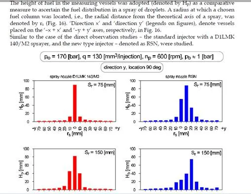
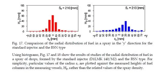
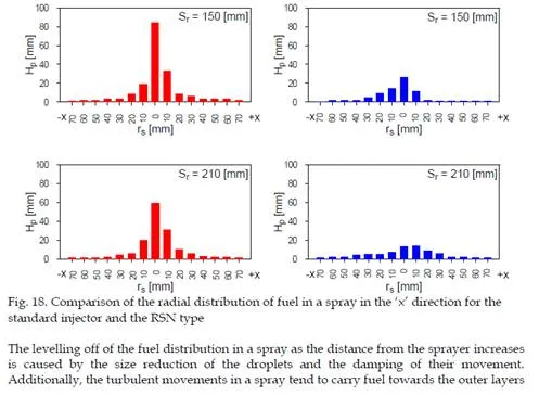
of the spray, and the distribution becomes more equal (Metz and Seika, 1998). This phenomenon is related to the fuel movement in the later phase of injection and it is also observed in the spray formed by the RSN-type injector. The levelling off of the fuel distribution with increased distance from the sprayer seems to be a phenomenon shared among sprays generated by both injector types.
A spray of fuel generated by the RSN sprayer shows asymmetry; the distribution in the ‘x’ direction differs from that in the ‘y’ direction. In the ‘y’ direction particularly, the concentration of fuel is considerably larger (also when the series of vessels is rotated through 45 deg). Moreover, in the ‘y’ direction a greater shift of the area of the maximum fuel concentration (core of a spray) may be observed in comparison to the ‘x’ direction. This leads to the conclusion that the fuel distribution in the spray formed by the RSN sprayer does not show any symmetry in relation to the theoretical axis of the spray.
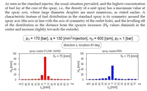
The largest shift of the spray core from the theoretical axis for the RSN sprayer was observed in the ‘y’ direction. This effect appeared when the axis of the sprayer was in one plane with the axis at –x + x. In this position the axis of the needle rotation was perpendicular to the ‘y’ direction. The asymmetry of the core of the spray generated by the RSN sprayer may be explained by the change of the cross-sections of the outlet holes and the resulting mechanical action of the surface of the hole in the sprayer body on the fuel being discharged. The fuel, flowing through the spraying hole (particularly in the opening phase), hit the surface of the outlet hole. This changed the direction of the flow, which caused variations in the position of the core in the cross-section of the spray.
The spray generated by standard injector is axially symmetric. More fuel saturation in the spray core causes a different value of combustion air factor. This is unfavourable, because soot is usually produced in the rich mixture area (local deficiency of air) at a sufficiently high temperature (800–1400 K). This happens mainly in the core of the fuel spray and at its rear, where the concentration of fuel droplets is often higher.
Executed investigations of radial distribution of fuel in spray confirm that the spray
generated by RSN injector is not symmetrical. The shift of the spray core outside (as effect of needle rotary) can be favourable on account of the possibly stronger impact of gas medium on spray zone, where the concentration of the fuel is higher. In this case, the secondary drop break-up will be more intensive. Smaller diameters of drops are obviously favourable with regard to soot and PM formation.
Conclusions
The parameters of the injection system have a decisive effect on the rate of combustion in the diesel engine, because of the influence on quality of formed air-fuel mixture. However, the optimal macrostructure of the spray, which is distributed in the cylinder volume, depends on the type and construction of the injector. On braking, the fuel stream in drops increases the area of contact between the fuel and air. It causes, first of all, fuel vaporisation and, then, its diffusion into air. The pressure energy generated by the injection system is consumed on spraying of the fuel stream which, together with the phenomena of physical and chemical parts of self-ignition delay, leads to fast increase in mixture entropy.
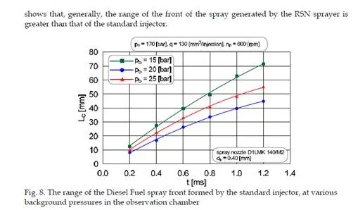
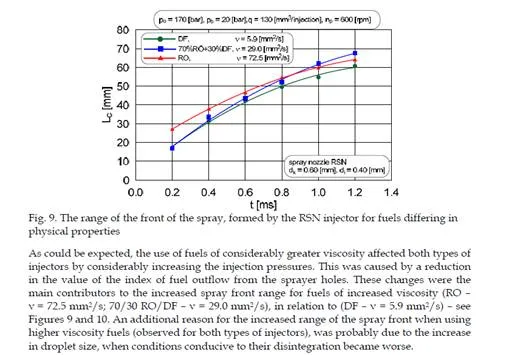
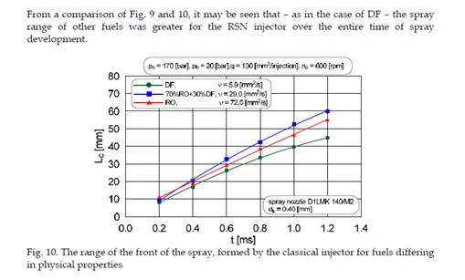
A better quality of fuel spraying guarantees RSN injector, which was confirmed by model investigations. The selected results have been presented in the paper.