Combustion of a fuel in the combustion chambers of a gas-turbine engine and a gas-turbine plant is closely connected with the processes of mixing (Lefebvre, 1985). Investigations of these processes carried out by both experimental and computational methods have recently become especially crucial because of the necessity of solving ecological problems.
One of the most pressing problems at present is account for the influence of droplets on an air flow. In some of the regimes of chamber operation this may lead to a substantial, almost twofold, change in the long range of a fuel spray and, consequently, to corresponding changes in the distributions of the concentrations of fuel phases.
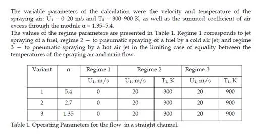
In this chapter physical models of the processes of interphase heat and mass transfer and computational techniques based on them are suggested. The present work is a continuation of research by Maiorova & Tretyakov, 2008. We set out to calculate the fields of air velocity and temperature as well as of the distribution of a liquid fuel in module combustion chambers with account for the processes of heating and evaporation of droplets in those regimes typical of combustion chambers in which there is a substantial interphase exchange. It is clear that when a “cold” fuel is supplied into a “hot” air flow, the droplets are heated and the air surrounding them is cooled. It is evident that at small flow rates of the fuel this cooling can be neglected. The aim of this work is to answer two questions: how much the air flow is cooled by fuel in the range of parameters typical of real combustion chambers, and how far the region of flow cooling extends. Moreover, the dependence of the flow characteristics on the means of fuel spraying (pressure atomizer, jetty or pneumatic) and also on the spraying air temperature is investigated.
Statement of the Problem
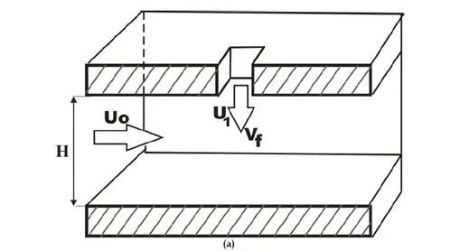
Schemes of calculated areas are presented on fig. 1. Calculations were carried out for the velocity and temperature of the main air flow U0 = 20 m s and T0 = 900 K, fuel velocity Vf =
8 m/s, fuel temperature Tf = 300 K. The gas pressure at the channel inlet was equal to 100
kPa.
The first model selected for investigation (fig. 1-a) is a straight channel of rectangular cross section 150 mm long into which air is supplied at a velocity U0 and temperature T0. It was
assumed that the stalling air flow at the inlet had a developed turbulent profile and that the spraying air had a uniform profile. Injection of a fuel with a temperature Tf into the channel at a velocity Vf is made through a hole in the upper wall of the channel with the aid of an injector installed along the normal to the longitudinal axis of the channel halfway between the side walls. In modeling the pneumatic injector it is considered that, coaxially with the fuel supply, the spraying air is fed at a velocity U1 and temperature T1 into the channel through a rectangular hole of size 4.5 ×3.75 mm. In modeling a jetty injector, we assume that the spraying air is absent.
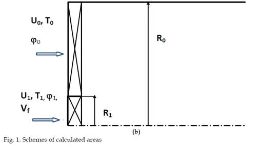
The second model (fig. 1-b) is the flow behind two coaxial tubes in radius of 5 and 40 mm, tube length is 240 mm. Heat-mass transfer of drop-forming fuel with the co-swirling two- phase turbulent gas flows is calculated. In this case injection of a fuel is made through a pressure or pneumatic atomizer along the longitudinal axis. Regime parameters corresponds regimes 2 and 3 from table 1 and α = 3.3. Inlet conditions were constant axial velocity, turbulent intensity and length. Axial swirlers are set in inlet sections. The tangential velocity set constant in the outer channel. The flow in the central tube exit section corresponded to solid body rotation law. The wane angles in inner and outer channels (1
and 0) varied from 0 to 65.
Calculation Technique
Calculations of the flow of a gas phase are based on numerical integration of the full system of stationary Reynolds equations and total enthalpy conservation equations written in Euler variables. The technique of allowing for the influence of droplets on a gas flow is based on the assumption that such an allowance can be made by introducing additional summands into the source terms of the mass, momentum, and energy conservation equations. The transfer equations were written in the following conservative form
thermally insulated. To find the coefficients of turbulent diffusion, use is made of the Boussinesq hypothesis on the linear dependence of the components of the tensor of turbulent stresses on the components of the tensor of deformation rates of average motion and two equations of transfer of turbulence characteristics (k–ε) in the modification that takes into account the influence of flow turbulence Reynolds numbers on the turbulent characteristics of flow (Chien, 1982). Here, the boundary conditions of zero velocity are imposed on the solid walls. For swirl flows calculations the model was modernized to take into account the swirl effect in turbulence structure (Koosinlin at al., 1974).
In the absence of chemical reactions the gas mixture is considered to consist of two components: kerosene vapors (with a molecular weight of 0.168 kg mole) and air (with a conventional molecular weight of 0.029 kg mole). For the mass fraction of kerosene vapors mf the equation of transfer of the type (1) is solved, and the mass fraction of air is determined from the condition under which the sums of the mass fractions of all the components are equal to unity.
The calculations of the distribution of fuel are based on the solution of a system of equations of motion, heating, and evaporation of individual droplets written in the Lagrange variables. The influence of turbulent pulsations onto the motion of droplets and on the change in their shape in the process of their motion is considered to be negligibly small. Then the equations that describe the processes of motion, heating, and evaporation have the following form:
Testing of the Calculation Technique
The first model (fig. 1-a) was originally used to test the calculation method. As a result of methodical calculations a finite-difference grid uniform in the x and z directions was selected. The grid along the y axis was made finer toward the channel walls according to the exponential law with exponent 0.91. The total number of nodes in the grid was 111筏111�41 =
505,161.
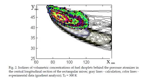
In experiences of authors it was spent laser visualization of a stream and postprocessing of photos by a method of the gradient analysis. The comparison on Fig.2 shows that the computational technique describes well the experimental data on the configuration of the fuel spray.
Results of Calculations
The results of calculation for the straight channel of rectangular cross section are presented in fig. 3 – 11. The velocity field in the vicinity of the place of fuel injection for the jetty (U1 =
0) and pneumatic (U1 = 20 m s) sprayings are given in Figs. 3 and 4, respectively. Here and
below, the results were made nondimensional through division by the characteristic dimension H = 50 mm, which is the height of the channel (R0 for the axisymmetric mixer), and by the characteristic velocity U0 = 20 m s.
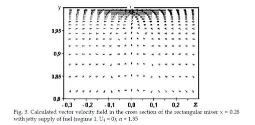
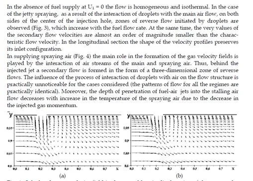
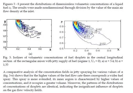
In the absence of fuel supply at U1 = 0 the flow is homogeneous and isothermal. In the case of the jetty spraying, as a result of the interaction of droplets with the main air flow, on both sides of the center of the injection hole, zones of reverse flow initiated by droplets are observed (Fig. 3), which increase with the fuel flow rate. At the same time, the very values of the secondary flow velocities are almost an order of magnitude smaller than the charac- teristic flow velocity. In the longitudinal section the shape of the velocity profiles preserves its inlet configuration.
 In supplying spraying air (Fig. 4) the main role in the formation of the gas velocity fields is played by the interaction of air streams of the main and spraying air. Thus, behind the injected jet a secondary flow is formed in the form of a three-dimensional zone of reverse flows. The influence of the process of interaction of droplets with air on the flow structure is practically unnoticeable for the cases considered (the patterns of flow for all the regimes are practically identical). Moreover, the depth of penetration of fuel-air jets into the stalling air flow decreases with increase in the temperature of the spraying air due to the decrease in the injected gas momentum
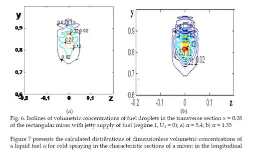
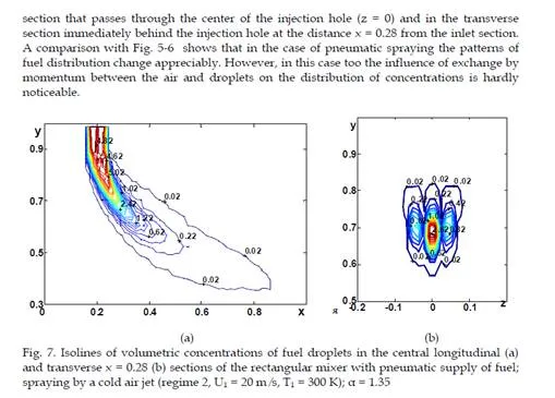
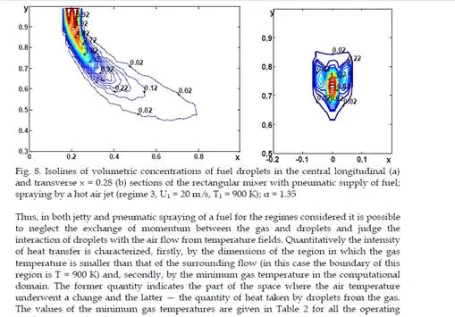
vortex structures in the distributions of both concentrations and temperatures in the transverse sections of the module. The lowering of the gas temperature occurs exclusively at the expense of interphase exchange. Vortex structures are clearly seen in transverse sections with pneumatic spraying on the graphs of the distribution of fuel concentrations. A comparison between the distributions of temperatures and concentrations in these cases shows that the concentration profiles are much narrower than the corresponding temperature profiles in both longitudinal and transverse directions. This is associated with the intense diffusion heat fluxes, with the droplets mainly following the air flow. Attention is also drawn to the fact that the penetrating ability of a “cold” fuel-air jet is higher than that of a “hot” one due to the following two reasons: the great energy of the “cold” jet and the more intense process of heating and evaporation of droplets in the “hot” jet.
A comparison of gas cooling in spraying of a fuel by a hot air jet and in jetty spraying shows that although the fuel is injected into flows with identical temperatures, in the second case the lowering of the gas temperature is more appreciable. This seems to be due to the fact that on injection of droplets into a stalling air flow the velocity of droplets relative to the gas is higher than in the case of injection into a cocurrent flow. The rate of the evaporation of droplets is also higher and, consequently, the complete evaporation of droplets occurs over smaller distances and in smaller volumes, thus leading to the effect noted. The total quantity of heat transferred from air to droplets is the same in both cases, but the differences observed allow one to make different fuel-air mixtures by supplying a fuel either into a cocurrent air flow or into a stalling one.
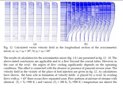
The results of calculation for the axisymmetric mixer (fig. 1-b ) are presented in fig. 12 – 18. The above-stated conclusions are applicable and to a flow beyond the coaxial tubes. However in the case of the swirl the region of flow cooling significantly depends on the operating conditions. This effect is connected with the absence or presence of paraxial reverse zone. The velocity field in the vicinity of the place of fuel injection are given in fig. 12. As calculations have shown, the basic role in formation of velocity fields is played by a swirl. In swirling flows with 1 > 45 there occurs flow separated zone. Flow patterns at mixture of streams with identical (T1 = T0 =900 K ) and various (T1 = 300 K, T0 =900 K ) temperature are almost the
same. The influence of the mean of spraying and the process of interaction of droplets with air on the flow structure is practically unnoticeable for the cases considered.
In fig. 13 – 14 pictures of trajectories of the droplets projected on longitudinal section of the mixer are resulted.
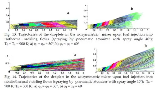
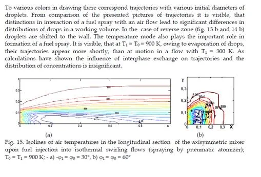
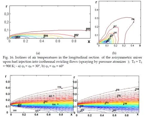
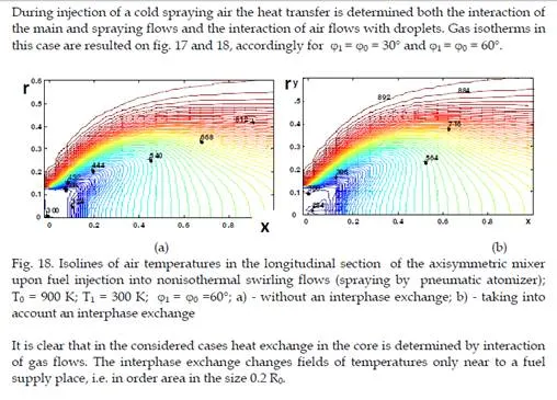
So just as in the case of rectangular mixer it is possible to neglect the exchange of momentum between the gas and droplets and to judge the interaction of droplets with an air flow from temperature fields. It’s clear that the greatest cooling of a gas flow by droplets occurs on the maximum gas temperature. The distributions of air temperatures on injection of a hot spraying air are given in Fig. 15. That temperature fields to the full are determined by the interaction of air flows with droplets. From comparison of drawings in fig 15 a) and b) it is visible, that areas of influence of droplets on a gas flow are various also they are determined in the core by flow hydrodynamics. In a case 1 = 0 = 30, the flow is no separated and the area of cooling of gas is stretched along an axis. In a case 1 = 0 = 60 there exists the paraxial reverse zone. As result the last droplets are shifted to the wall together with cooled gas. Analogous isothermals of gas at fuel spraying from one source (supply by pressure atomizer) are resulted in fig. 16 a) and `16 b).
Conclusions
In all means of spraying, for the regimes considered it is possible to neglect the exchange of momentum between the gas and droplets and to judge the interaction of droplets with an air flow from temperature fields.
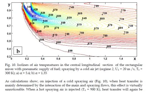
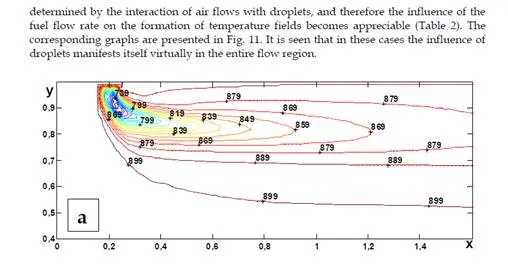
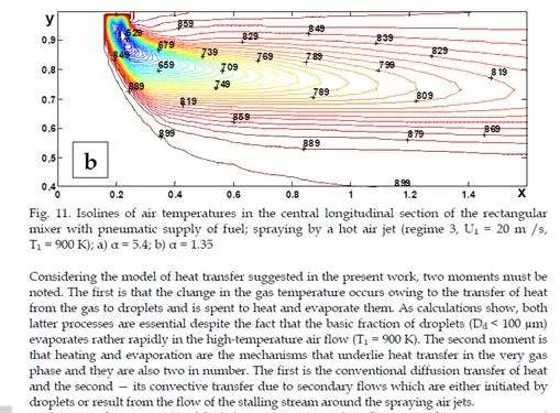
Injection of a fuel by a jet injector may cause a substantial change in the gas temperature. In the given case it occurs due to heat transfer from the gas to droplets and is spent on their heating and evaporation. In the case of pneumatic spraying of a fuel by a cold air jet the influence of interphase exchange is insignificant. Heat transfer is predominantly determined by the interaction of the main and spraying flows. During injection of a hot spraying air, when heat transfer inside the gas flow is less intense, the influence of the injection of a fuel on the formation of temperature fields again becomes appreciable. However, in this case the gas is cooled less than in jetty spraying. This effect is due to the fact that when droplets are injected into a stalling air flow, the rate of their evaporation is higher than during injection into a cocurrent flow.
In the case of the swirl the region of flow cooling significantly depends on the operating conditions. This effect is connected with the absence or presence of paraxial reverse zone.
The conclusions drawn confirm the necessity of taking into account the processes of interphase heat and mass exchange when investigating the mixture formation.


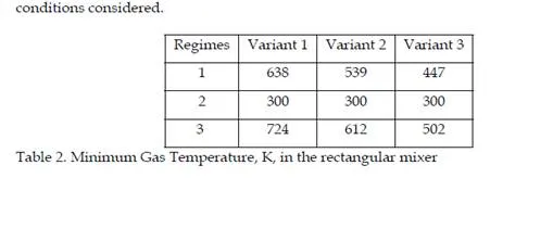
Comments are closed