The scramjet engine is one of the most promising propulsive systems for future hypersonic vehicles. Over the last fifty years the scramjet engine technology has been intensively investigated and several such engines have been flight-tested in recent years (Neal, Michael,
& Allan, 2005; Paul, Vincent, Luat, & Jeryl, 2004). Research on supersonic combustion technologies is of great significance for the design of the engine and many researchers pay significant attention to the hypersonic airbreathing propulsion. The mixing and diffusive combustion of fuel and air in conventional scramjet engines take place simultaneously in the combustor (Huang, Qin, Luo, & Wang, 2010). Since the incoming supersonic flow can stay in the combustor only for a very short period of time, i.e. of the order of milliseconds (Aso, Inoue, Yamaguchi, & Tani, 2009; Huang et al., 2010; Hyungseok, Hui, Jaewoo, & Yunghwan,
2009), and the whole process of combustion has to be completed within this short duration, this is a significant restriction to the design of the scramjet engine. In order to solve this problem, hydrogen, one of the most promising fuels for the airbreathing engine with ~10 times faster reaction than hydrocarbons, is widely used in the scramjet combustor.
In recent years, a cavity flameholder, which is an integrated fuel injection/flame-holding approach, has been proposed as a new concept for flame holding and stabilization in supersonic combustors (Alejandro, Joseph, & Viswanath, 2010; Chadwick et al., 2005; Chadwick, Sulabh, & James, 2007; Daniel & James, 2009; Gu, Chen, & Chang, 2009; Jeong, O’Byrne, Jeung, & Houwong, 2008; Kyung, Seung, & Cho, 2004; Sun, Geng, Liang, & Wang,
2009; Vikramaditya & Kurian, 2009). The presence of a cavity on an aerodynamic surface could have a significant impact on the flow surrounding it. The flow field inside a cavity flameholder is characterized by the recirculation flow that increases the residence time of the fluid entering the cavity, and the cavity flame provides a source of heat and radicals to ignite and stabilize the combustion in the core flow.
However, so far, the flow field in the scramjet combustor with multiple cavity flameholders has been rarely discussed, and this is an important issue as it can provide some useful guidance for the further design of the scramjet combustor. Multi-cavity flameholder can
produce larger drag forces on the scramjet combustor, as well as improve the combustion efficiency of the combustor. A balance between these two aspects will be very important in the future design of the propulsion system in hypersonic vehicles. At the same time, the combustor configuration, i.e. the divergence angle of each stage, makes a large difference to the performance of the combustor. Researchers have shown that (Huang, Li, Wu, & Wang,
2009) the effect of the divergence angles of the posterior stages on the performance of the scramjet combustor is the most important, and the effect of the divergence angle on the first stage is the least important. When the location of the fuel injection moves forward, the effect of the divergence angle of the former stages becomes more important.
In this chapter, the two-dimensional coupled implicit Reynolds Averaged Navier-Stokes (RANS) equations, the standard k–ε turbulence model (Huang & Wang, 2009; Launder & Spalding, 1974) and the finite-rate/eddy-dissipation reaction model (Nardo, Calchetti, Mongiello, Giammartini, & Rufoloni, 2009) have been employed to investigate the effect of the location of the fuel injection on the combustion flow field of a typical hydrogen-fueled scramjet combustor with multi-cavities.
Physical model and numerical method
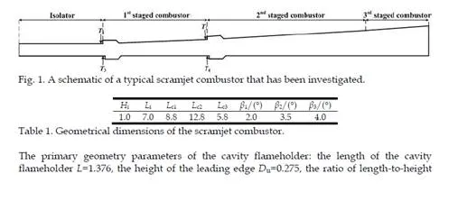
The engine investigated adopts the single-expanded combustor and fractional combustion mode, and it consists of an isolator and three staged combustors, see Fig. 1. There are four cavity flame holders located on the upper and lower walls of the first and the second staged combustors, respectively. Hydrogen is injected from the slot, located at 5mm from the leading edge of the four cavity flame holders on both the upper and lower walls of the first and the second staged combustor. The width of the slot is 1mm.
Assuming that the height of the isolator Hi is 1 unit, the distance between the upstream forward face of the cavity flameholder in the upper wall and that in the lower wall of each staged combustor is 0.183 along the x axis. The dimensions of the components of the scramjet combustor are shown in Table.1, where Li, Lc1, Lc2 and Lc3 are the lengths of the isolator, the first staged combustor, the second staged combustor and the third staged combustor, respectively. The divergence angles of the first staged combustor, β1, the second staged combustor, β2 and the third staged combustor, β3 are 2.0 degree, 3.5 degree and 4.0 degree, respectively.
In the CFD model, the standard k–ε turbulence model is selected. This is because of its robustness and its ability to fit the initial iteration, design lectotype and parametric investigation. Further, because of the intense turbulent combustion effects, the finite- rate/eddy-dissipation reaction model is adopted. The finite-rate/eddy dissipation model is based on the hypothesis of infinitely fast reactions and the reaction rate is controlled by the turbulent mixing. Both the Arrhenius rate and the mixing rate are calculated and the smaller of the two rates is used for the turbulent combustion (FLUENT, 2006). While a no-slip condition is applied along the wall surface, at the outflow all the physical variables are extrapolated from the internal cells due to the flow being supersonic.
Model validation
In order to validate the present numerical method for computing these complex fluid flows in the scramjet combustor with multi-cavities, three computational cases are investigated, namely, the problems of an injection flow, a cavity flow and a fuel-rich combustion flow. The grids for the geometries are structured and generated by the commercial software Gambit, and the grids are distributed more densely near the walls and in the vicinity of the shock wave generation in order to resolve the boundary layers.
Injection flow
In this first case, the physical model that was experimentally investigated by Weidner et al.(Weidner & Drummond, 1981) is employed since the model has a good two-dimensional structure and it can be used to validate the correctness of the injection phenomenon in the scramjet combustor.
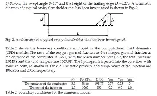
The experimental test investigates the phenomenon of the traverse injection of helium into parallel air flow, namely θ=90°, and the setup of the experiment is schematically shown in Fig. 3. The air stream is introduced from the left hand side of a rectangular channel which is
25.4cm long and 7.62cm high. The static pressure of the air stream is P=0.0663MPa, the static temperature is T=108.0K and the March number is M=2.9. The helium is injected at sonic condition from a 0.0559cm slot into an air stream from the bottom surface of the rectangular channel at a location which is 17.8cm downstream from the entrance of the channel. The flow conditions for the helium at the slot exit are P=1.24MPa, T=217.0K and M=1.0.
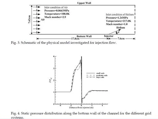
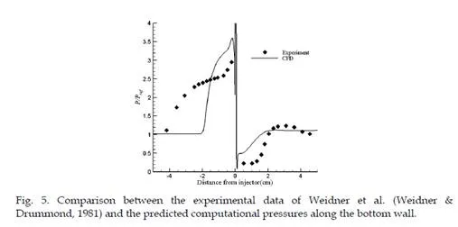
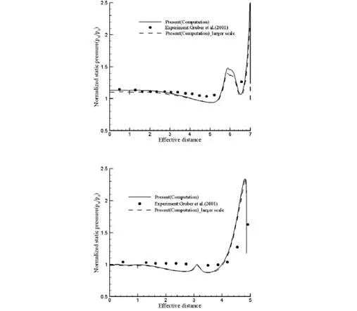
In order to investigate grid independency of the numerical simulations, three sets of mesh with different numbers of cells have been employed, namely approximately 19,200, 38,080 and 76,230 cells, respectively. Fig. 4 shows the static pressure distribution along the bottom wall of the channel for the three different grids. It is observed that the shock wave can be captured accurately for all three different grid scales, and the pressure distributions along the bottom wall of the channel in the downstream region of the injection slot are almost the same for the three grids employed. With different grid scales, the location of the disappearance of the reattachment region and the location of the generated shock wave can
be predicted reasonably accurately when compared with the experimental data, see Fig. 5. This means that the difference in the three grid systems employed in the simulations makes only a small difference to the numerical predictions for the interaction between the air stream and the injection.
Fig. 5 shows a comparison between the experimental data and the computational predictions for the pressure along the bottom wall. The reference pressure Pref is 0.0663MPa. It is observed that the computational results obtained in this investigation show good qualitative agreement with the experimental data for both the upstream and downstream regions of the injection.
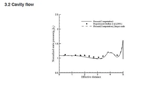
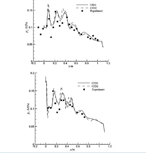
and the experimental data of Wang Chun et al. (Wang et al., 2000). The solid line represents the numerical results from the coarse mesh, CFD1, and the dashed line is for CFD2. It can be observed that the static pressure distributions on the top and bottom walls obtained by the CFD results show good qualitative agreement with the experimental results. The CFD model captures the shock wave reasonably well in terms of both the location and strength of the wave system. The pressure disturbance on the top and bottom walls is due to the compression and expansion of the flow that occurs alternately in the mixing and expansion sections of the combustor caused by the shock wave system. At the entrance to the mixing section of the combustor, due to the differences in the flow parameters in the two supersonic flows of air and hot streams, and the effect of the clapboard, the expansion wave appears during flow expansions. When the two flows intersect, the flow direction changes, and the two flows become compressed (Situ, Wang, Niu, Wang, & Lu, 1999). It is concluded that the CFD approach used in this investigation can reasonably accurately simulate these physical phenomena in the scramjet combustor
Results and discussion
In order to discuss the influence of the fuel injection location on the flow field of the scramjet combustor with multiple cavity flameholders, three sets of the fuel injection location are employed in this investigation, namely, T2, T4 and both T2 & T4, in Fig. 1. The other fuel injection locations are not considered here, i.e. T1 or T3, because placing the fuel injection location closer to the entrance of the combustor and more concentrated in a certain distance can be of much assistance in the optimization of the performance of the combustor, but the fuel injection location being excessively close to the entrance of the combustor can cause the interaction between the isolator and the combustor to occur more easily and push the shock wave forward, and this will cause the inlet unstart (Wu, Li, Ding, Liu, & Wang, 2007).
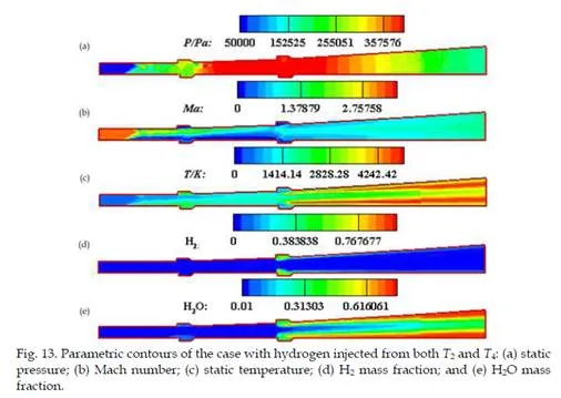
Figs. 11-13 show the parametric contours of the cases with the hydrogen injected from T2, T4 and both T2 & T4, respectively. When the hydrogen is injected from both T2 and T4, the shock wave in the combustor is pushed forwards into the isolator by the intense combustion and a high static pressure region formed between the first upper cavity flameholder and the second upper cavity flameholder, see Fig. 13 (a). Then if the fuel injection location moves forward, i.e. T1 or T3, the shock wave is pushed out of the isolator into the inlet and this causes the inlet unstart.
There exits a complex shock wave system in the combustor. When the hydrogen is injected from T2, the shock waves generated from the leading edges of the first upper and lower cavity flameholders interact and form a high pressure region, see Fig. 11 (a). At the same time, we observe that the high pressure region exists mainly in the vicinity of the injection due to the fuel combustion. There is a low Mach number region generated on the upper wall of the combustor due to the fuel injection, see Fig. 11 (b). Meanwhile, due to the interaction between the shock wave and the boundary layer, there exists a separation region on the lower wall of the combustor, see Fig. 14 (a). The fuel injection makes the vortices in the cavity flameholder become larger and it deflects into the core flow. The shear layer formed on the leading edge of the second upper cavity flameholder impinges on its trailing edge, and there are almost no vortices in the first upper and lower cavity flameholders. The region in the cavity flameholders acts as a pool to provide the energy to ignite the fuel and prolong the residence time of the flow in the combustor. The Mach number in the cavity flameholders is much lower than that in any other place of the combustor, except in the separation regions, see Fig. 11 (b), and the static temperature in the cavity flameholders is slightly higher than that in the core flow, see Fig. 11 (c). If we change the geometry of the cavity flameholder, it can act as an ignitor in the scramjet combustor, but we should
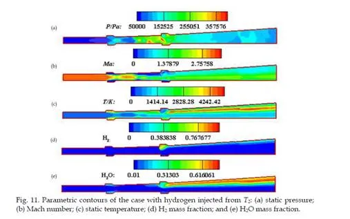
consider the material of the cavity when operating at such high temperatures. Further, the combustion of the hydrogen takes place near the upper wall of the combustor, see Fig. 11 (d), and the combustion product, namely, H2O mainly distributes along the upper wall. There is also a small combustion production in the first upper and lower cavity flameholders, see Fig.
11 (e), and it is brought forward by the recirculation zone.
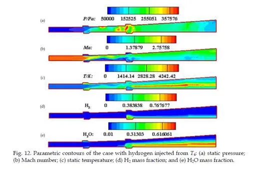
When the hydrogen is injected into the core flow from T4, the shock wave generated from the leading edge of the first upper cavity flameholder is much weaker than that generated from the leading edge of the first lower cavity flameholder, and this makes the shock wave, after the interaction, deflect into the upper wall of the combustor. Further, we can observe a high pressure region generated in the vicinity of the upper wall, see Fig. 12 (a), and this is different from the case with the hydrogen injected from T2. The reason may lie in the differences in the fuel injection locations. At the same time, we observe two low Mach number regions on the lower wall of the scramjet combustor and this has been caused by the recirculation zones, see Fig. 12 (b) and Fig. 14 (b), and because of the interaction of the shock wave and the boundary layer, there also exists a separation area in the vicinity of the upper wall of the combustor.
Because of the variation in the fuel injection location and the effect of the shock wave, small eddies are formed in both the upper and lower cavities of the first flameholders, and it lies on the rear edge of the cavity, see Fig. 14 (b). The vortices can act as a recirculation zone for the mixture. At this condition, if the fuel is injected from the first staged combustor simultaneously, the performance of the combustor will be improved since the residence time is longer than in the case when the hydrogen is injected from T2. Meanwhile, the
distributions of the fuel and the combustion production are opposite to the case when the hydrogen is injected from T2, and they mainly distribute along the lower wall of the scramjet combustor because of the fuel injection location, see Fig. 12(d) and (e). Due to the fuel injection being before the cavity flameholder, the eddy generated in the second lower cavity flameholder become larger than before, see Fig. 14 (b), namely the case without fuel injection before the cavity flameholder. The eddy is deflected into the core flow, and the shear layer generated at the leading edge of the second lower cavity flameholder impinges on its trailing edge.
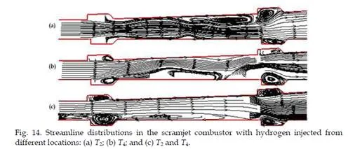
When the hydrogen is injected from both T2 and T4, the flow field is the most complex in the combustor, see Fig. 13. At this condition, the shock wave is pushed out of the combustor because of the intense combustion, and a larger low Mach number region is generated on the lower wall of the combustor because of the stronger interaction between the shock wave and the boundary-layer, see Fig. 13 (b), and it spreads forward to the lower wall of the isolator. A higher static pressure is obtained in the region between the first and the second cavity flameholder, see Fig. 13 (a), and this is the main cause for the spreading forward of the shock wave. Due to the hydrogen injected from both T2 and T4, the fuel and the combustion product distribute both on the upper and lower walls of the combustor, see Fig.
13 (d) and (e), and the combustion occurs mainly in the vicinity of the walls. This illustrates that the injection pressure is not high enough to make the fuel penetrate deeper. The recirculation zone generated at this condition is much larger than that formed in the other two cases, and thus the flow can stay in the combustor much longer, see Fig. 14(c). While travelling over the cavity, the injected hydrogen interacts with the strong trailing edge shock wave, which plays an important role in the combustion. The trailing edge shock wave can improve the static pressure and the static temperature of the flow in the vicinity of the trailing edge of the cavity flameholder, and this can also benefit the combustion.
Conclusion
In this chapter, the two-dimensional coupled implicit RANS equations, the standard k-ε turbulence model and the finite-rate/eddy-dissipation reaction model are introduced to simulate the combustion flow field of the scramjet combustor with multiple cavity flameholders. The effect of the fuel injection location on the flow field of the combustor has been investigated. We observe the following:
The numerical methods employed in this chapter can be used to accurately simulate the combustion flow field of the scramjet combustor, and predict the development status of the shock wave.
The fuel injection location makes a large difference to the combustion flow field of the scramjet combustor with multiple cavity flameholders. The flow field for the case with hydrogen injected from both T2 and T4 is the most complex, and in this situation the shock wave has been pushed forward into the isolator. This causes the boundary layer to separate, generates a large recirculation zone and reduces the entrance region of the inflow. If the fuel injection location moves slightly forward, the shock wave may be pushed out of the isolator, and into the inlet. This will do damage to the inlet start.
The fuel injection location changes the generation process of the vortices in the cavity flameholders to some extent. When the hydrogen is injected from T2, there is no vortex formation in both the upper and lower cavity of the first flameholder. When the hydrogen is injected from T4, small eddies are generated in the first upper and lower cavity flameholders. Further, if the hydrogen is injected from both T2 and T4, the eddies in the first upper and lower cavity flameholders become larger, and this is due to the spread of the shock wave pushed by the higher static pressure because of the more intense combustion.
The fuel injection varies the dimension of the eddy generated in the nearby cavity flameholder. Due to the fuel injection, the eddy generated in the nearby cavity flameholder becomes larger, over the cavity and deflects into the core flow. This makes a larger recirculation zone than the case without fuel injection.
The cavity is a good choice to stabilize the flame in the hypersonic flow, and it generates a recirculation zone in the scramjet combustor. Further, if its geometry can be designed properly, it can act as an ignitor for the fuel combustion, but the material of the cavity flameholder should be considered for operating at those high temperatures.

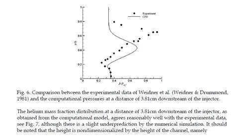
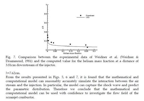
Comments are closed