In these times injection is the basic solution of supplying of fuel in the Spark-Ignition (SI) engines. The systems of fuel injection were characterized by different place of supplying of fuel into the engine. Regardless of the sophistication of control system, the following types of fuel injection systems can be identified:
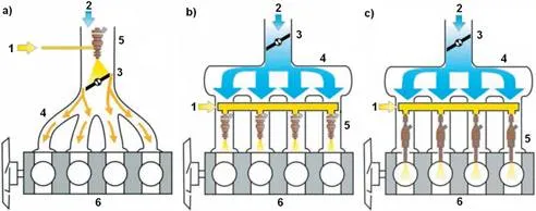
· injection upstream of the throttle, common for all of the cylinders – called Throttle Body Injection – TBI or Single Point Injection – SPI (Figure 1 a),
· injection into the individual intake channels of each cylinder – called Port Fuel Injection – PFI or Multipoint Injection – MPI (Figure 1 b),
· injection directly into the each cylinder, Direct Injection – DI (Figure 1 c).
HISTORICAL BACKGROUND OF APPLICATION OF FUEL INJECTION SYSTEMS IN SI ENGINES
The history of application of fuel injection for spark-ignition engines as an alternative for unreliable carburettor dates back to the turn of the 19th and 20th century. The first attempt of application of the fuel injection system for the spark-ignition engine took place in the year 1898, when the Deutz company used a slider-type injection pump into its stationary engine fuelled by kerosene. Also fuel supply system of the first Wright brothers airplane from 1903 one can recognize as simple, gravity feed, petrol injection system [2]. Implementation of a Venturi nozzle into the carburettor in the following years and various technological and material problems reduced the development of fuel injection systems in spark-ignition engines for two next decades. The wish to get better power to displacement ratio than a value obtained with the carburettor, caused the return to the concept of fuel injection. This resulted that the first engines with petrol injection were used as propulsion of vehicles before World War 2nd. In the aviation industry the development of direct fuel injection systems took place just before and during World War 2nd, mainly due to Bosch company, which since 1912 had conducted research on the fuel injection pump. The world’s first direct-injection SI engine is considered Junkers Jumo 210G power unit developed in the mid-30’s of the last century and used in 1937 in one of the development versions of Messerschmitt Bf-109 fighter [3].
After the Second World War, attempts were made to use the fuel injection into the two-stroke engines to reduce fuel loss in the process of scavenging of cylinder. Two-stroke spark-ignition engines with mechanical fuel injection into the cylinder were used in the German small cars Borgward Goliath GP700 and Gutbrod Superior 600 produced in the 50’s of 20th century, but without greater success. Four-stroke engine with petrol direct injection was applied for the first time as standard in the sports car Mercedes-Benz 300 SL in 1955 [4]. Dynamic expansion of automotive industry in subsequent years caused that the aspect of environmental pollution by motor vehicles has become a priority. In combination with the development of electronic systems and lower their prices, it resulted in an rejection of carburettor as a primary device in fuel supplying system of SI engine in favour of injection systems. Initially the injection systems were simplified devices based on an analogue electronics or with mechanical or mechanical-hydraulic control. In the next years more advanced digital injection systems came into use. Nowadays, injection system is integrated with ignition system in one device and it also controls auxiliary systems such as variable valve timing and exhaust gas recirculation. Electronic control unit of the engine is joined in network with other control modules like ABS, traction control and electronic stability program. This is necessary to correlate operation of above mentioned systems.
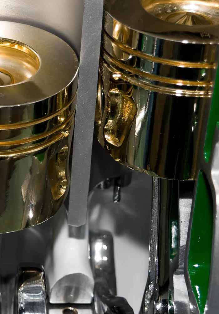
The last decade of the 20th century can be considered as the ultimate twilight of carburettor, a device which dominated for about 100 years in fuel systems for spark-ignition engines. Also the production of continuous injection fuel systems was terminated. Due to the successive introduction of increasingly stringent standards for exhaust emission, central injection systems had to give way to multi-point injection systems even in the smallest engines of vehicles. In the late 90’s on market appeared again vehicles using spark-ignition engines with direct fuel injection. This is the most accurate method for the supply of fuel. An important advantage of the direct-injection consists in the fact that the evaporation of the fuel takes place only in the volume of the cylinder resulting in cooling of the charge and, consequently, an increase in the volumetric efficiency of the cylinder [5]. In 1996, the Japanese company Mitsubishi launched production of 1.8 L 4G93 GDI engine for Carisma model. The new engine had 10% more power and torque and 20% lower fuel consumption in comparison with the previously used engine with multipoint injection system. Figure 2 presents the cross-section of the cylinder of GDI engine with vertical intake channel and a view of the piston with a crown with a characteristic bowl.
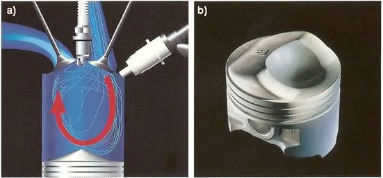
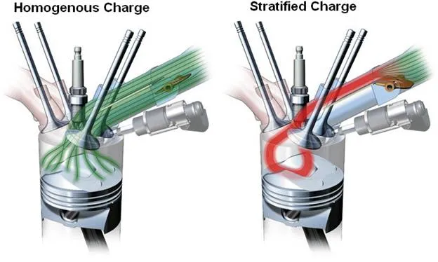
In the next years also another automotive concerns applied various SI engines with gasoline direct injection. One should mention here D4 engines of Toyota, FSI of Volkswagen, HPi of Peugeot – Citroën group, SCi of Ford, IDE of Renault, CGi of Daimler-Benz or JTS of Alfa Romeo. Process of the forming of homogeneous and stratified mixture in the FSI engine was presented in Figure 3.
In 2005 D-4S injection system was presented by Toyota Corporation. This injection system joins features of MPI and DI systems. It is characterized by occurrence of two injectors for each cylinder of an engine. Implementation of such a sophisticated injection system gives increase in engine’s performance and lower fuel consumption in relation to engines with both types of fuel supplying: multipoint system and direct injection system.
THE TOYOTA D-4S DUAL-INJECTION SYSTEM
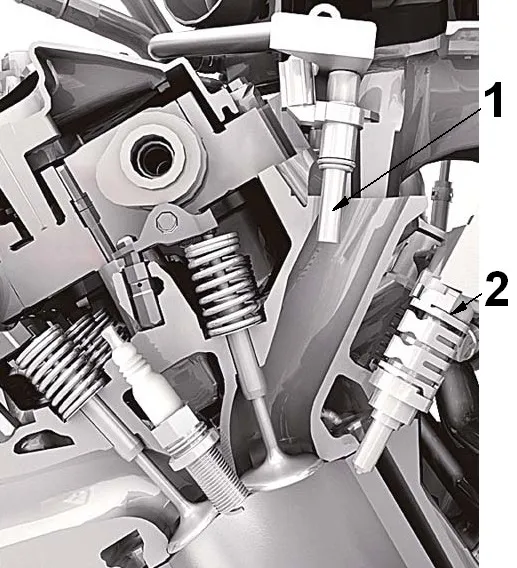
In August 2005 the innovative fuel injection system was implemented by Toyota into naturally aspirated 2GR-FSE engine used in sports saloon called Lexus IS350 [7]. This engine has got very good performance joined with moderate fuel consumption and very low exhaust emission. On the US market Lexus IS350 is qualified as Super Ultra Low Emission Vehicle [8]. The most specific feature of 2GR-FSE engine is using of two injectors for each cylinder. One of them supplies the fuel into the cylinder and the second one delivers it into the appropriate intake channel. The location of injectors in the engine was presented in Figure 4.
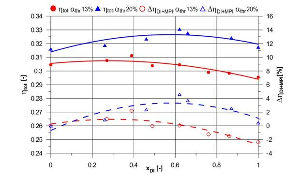
The fraction xDI of fuel supplied directly into the combustion chamber into the whole mass of fuel is dependent on engine speed and load. At the part-load the fuel mass is divided into two fuel systems in such a way that at least 30% of fuel is injected directly, what protects direct fuel injectors against overheating.
On the basis of the analysis of the combustion process, it was found that for the partial load, the two-point (per one cylinder) injection of fuel causes a more favourable distribution of the air to fuel ratio in the volume of the cylinder than in the case when the total mass of the fuel is injected to the intake pipe, or directly into the cylinder [10]. The mixture is more homogeneous. Only around the spark plug electrodes, it is slightly enriched with respect to the stoichiometric composition, which shortens the induction period and influences positively the combustion process. Figure 5 shows the results of measurements of propagation of the flame front in the combustion chamber by 21 ionization probes for indirect injection (xDI = 0), direct injection (xDI = 1) and the 30% mass of fuel injected directly into the cylinder (xDI = 0.3).
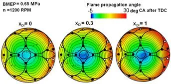
· One can see that for those conditions the flame front propagates fastest when 30% of mass of the fuel is injected directly into the combustion chamber. It allows to increase the torque by the engine.
On the Figure 6 the chart of the fraction xDI of mass of fuel injected directly into the cylinder for the whole 2GR-FSE engine map was presented.
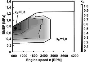
· The engine works in the whole speed range only with direct fuel injection at low load, that is up to about 0.28 MPa of BMEP (brake mean effective pressure) and for the engine speed higher than 2800 RPM, irrespective of the engine load. As it was mentioned above, in the rest of map, the fuel is divided between two injection systems: direct and multipoint.
The application of such a sophisticated fuel injection system, besides of improvement of the torque curve, gives lower fuel consumption of the engine. The 2GR-FSE engine fuel consumption map with marked point on the lowest specific fuel consumption was presented in Figure 7.
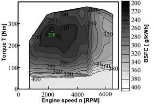
· Analyzing Figure 6 and 7 it can be observed that the area of engine fuel consumption map with lowest specific fuel consumption, i.e. ≤ 230 g/kWh was obtained with dual-injection of fuel. Above-mentioned value of specific fuel consumption corresponds to the engine total efficiency equal to 0.356. In the present state of development of internal combustion engines this result can be considered very good, especially since it was achieved with a stoichiometric mixture, without stratification proper for engines working on lean mixtures. The use of two injectors per cylinder also enabled to remove the additional flap closing one of the intake channels used in the D-4 system [11] for each cylinder when the engine is running at low speed. Removal of flap system has also a positive effect on the improvement of the volumetric efficiency of the engine with dual-injection system, especially for the higher speed at wide open throttle.
One of the components of D-4S system, which had a great impact on improving fuel mixture formation in the cylinder was the direct fuel injector forming a dual fan-shaped stream. It was developed specifically for the 2GR-FSE engine. Modification of the shape of the injector nozzle for the engine used 2GR-FSE has the effect of increasing the degree of homogeneity of the mixture in the cylinder. An example of a visualization of the distribution of the air-fuel ratio in the combustion chamber cross-section performed with Star-CD v.3.150A-tool was shown in Figure 8.
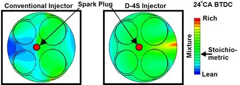
· Distribution of the air to fuel ratio in the combustion chamber for the mixture formed by the injector of new type is much more favourable. In this case the cylinder charge is not homogeneous only at the border of the combustion chamber. There is no undesirable variation in the mixture composition near spark plug electrodes.
The direct fuel injector has got a nozzle in a form of two rectangular orifices with dimensions 0.52 x 0.13 mm. It works at pressure from range between 4 and 13 MPa. Fuel flow at the pressure 12 MPa equals to 948 cm3 per minute. On the other hand in the indirect injection system 12-hole injectors were used. The indirect fuel injectors work at pressure 0.4 MPa. At this pressure its fuel flow is equal to 295 cm3 per minute.
In summary, the issue of spark-ignition engine with the dual-injection fuel system is highly interesting and, just as importantly, very current. This happens especially because of the possibility of reduction of CO2 and toxic exhaust gas emissions into the atmosphere using of dual-injection fuel systems. In consequence, the authors took the issue to determine the impact of the application of dual-injection fuel system on work parameters of engine with a much lower displacement than is the case of mass produced engines.
The objective of the study was to evaluate the impact of distribution of fuel in dual-injection supply system on its performance and exhaust emissions for specific points in the engine operation range.
The object of investigations
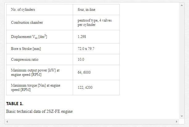
· As the object of both simulations and experimental research a four-stroke spark-ignition engine of type 2SZ-FE produced by Toyota for the Yaris car was chosen. The main part of the undertaken work was bench testing. Simulation studies were also performed in order to understand the phenomena that could not be determined during the experimental research, e.g. visualisation of the injection and combustion or formation of the selected components of exhaust gas. In the Table 1the basic technical data of the test engine were shown.
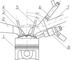
In comparison with original engine, this one was significantly redesigned. High pressure fuel injectors were mounted into a cylinder head of the engine in order to achieve fuel injection into combustion chambers of each cylinder. The implemented injectors were made by Bosch and were used, among others, to FSI engines from Volkswagen with petrol direct injection. The injectors was mounted at an angle 68 degrees to vertical axis of the cylinder, i.e. parallel to the axis of the intake channel at the point of mounting of the intake manifold. The location of injectors of direct and indirect fuel supply system was presented on Figure 9.
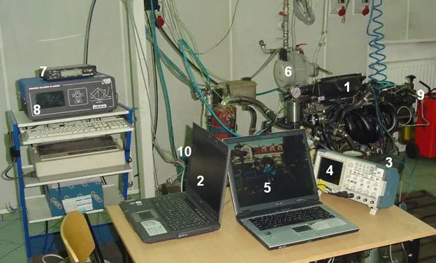
The engine was mounted on the test stand and joined with an Eddy-current dyno. The dyno has electronic system of measure and control, which can be connected to a PC for easy data acquisition. In order to meet the goals the original engine control unit has been replaced with a management system which can be programmable in real time. Such a system has the ability to control ignition system, injection system and various other systems. An important feature of the system is the possibility of independent control of injection time and timing for the two sets of injectors and closed-loop operation with wideband oxygen sensor LSU 4.2 type. Another device used to operate the high-pressure injector was peak & hold-driver working at voltage of about 100V. The overall view of the test stand was presented on Figure 10.
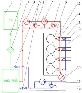
The scheme of the fuel supply system was shown in Figure 11. The direct injection and multipoint injection systems was separated on the diagram. The indirect injection system was marked in blue, the direct injection system was marked in red and elements common for both of the systems were marked in green. The mass flow of fuel in direct and indirect circuit of injection system was measured by the gravimetric flow meter.
Experimental studies
This piece of work presents the results of the tests of engine, during which distribution of fuel between the direct injection system and port injection system was changed.
For each test the constant injection and ignition timing and the stoichiometric composition of the mixture was maintained. The direct injection timing was determined in preliminary tests at 281° CA before TDC, which means direct injection of fuel during the intake stroke. Also during the preliminary test of the engine the pressure of direct fuel injection was set at 8 MPa. The injection time for both of the fuel supply systems was adjusted so as to maintain a stoichiometric mixture composition at different values of the fraction of fuel injected directly into the cylinder xDI.
IMPACT OF THE APPLICATION OF DUAL-INJECTION SYSTEM ON THE PERFORMANCE AND FUEL CONSUMPTION
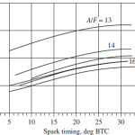
On the basis of results of the above mentioned tests, the curves of torque T and brake specific fuel consumption BSFC in a function of the fraction of fuel injected directly into the cylinder xDI were obtained. Figure 12 shows the traces of torque and specific fuel consumption approximated by parabolas obtained at the throttle opening 13% and engine rotational speed 2000 RPM.
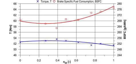
For the case shown in this figure, it is seen that the maximum torque and minimum specific fuel consumption were obtained for the fraction of fuel injected directly into the cylinder xDI equal to nearly 0.4. The results obtained with this distribution of fuel between the direct injection system and port injection system show significant differences especially in comparison with the test results obtained when the entire amount of fuel is injected directly into the cylinder.
Curves of torque and specific fuel consumption as a function of the fraction of fuel injected directly into the cylinder xDI obtained at 2000 RPM and throttle opening of 20% are shown in Figure 13.
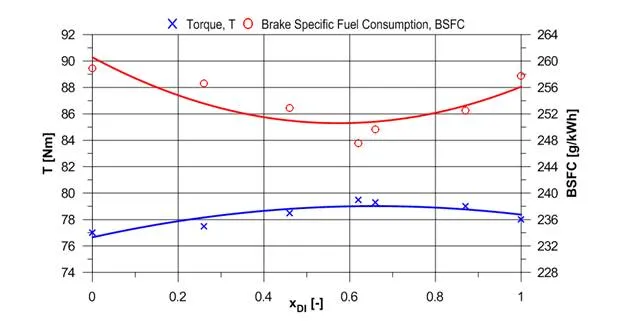
· For the throttle opening equal to 20% and engine speed 2000 RPM best results of specific fuel consumption and torque was observed for the ratio of fuel injected directly into the cylinder amounting to 0.62. In the described case, the mentioned operating parameters of the engine received a significant improvement in relation to the situation when the whole amount of the fuel is injected into intake channels.
Figure 14 shows charts of engine total efficiency and relative increase of the engine total efficiency ΔηDI + MPI for dual-injection operation in relation to operation with indirect fuel injection developed on the basis of the results of Figure 12 and Figure 13. The traces shown on Figure 14 are the result of parabolic approximation the points obtained by the calculations.
EXHAUST GAS COMPOSITION AT OPERATION WITH DUAL-INJECTION
· During the described above tests of the engine using gas analyzer Arcon Oliver K-4500 volumetric concentrations of individual exhaust components in the exhaust manifold were measured The concentration of carbon monoxide CO, carbon dioxide CO2, nitric oxide NO, unburned hydrocarbons HC and additionally exhaust gas temperature texh were investigated. The total concentration of hydrocarbons in the exhaust HC was converted by the gas analyzer to hexane.
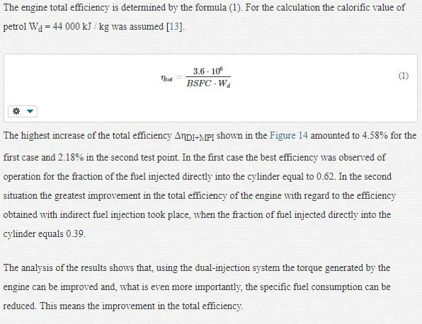
In Figure 15 registered at speed 2000 RPM and at throttle opening of 13% the traces of volumetric concentrations of the above mentioned chemicals and the exhaust gas temperature were shown depending on the fraction of fuel injected directly into the cylinder.
· The analysis of Figure 15 shows that with increase in the fraction of fuel injected directly into the cylinder the concentrations of carbon monoxide and hydrocarbons increase slightly, while the concentrations of nitrogen oxide and carbon dioxide decrease. Also the temperature of gas leaving the engine cylinders decreased slightly. The difference between the NO concentration for injection only into the intake channel and only with direct injection into the cylinder is not high and is approximately 170 ppm. The concentration of HC for direct injection in a similar comparison is increased somewhat more, but without reaching the particularly high value – approximately 290 ppm.
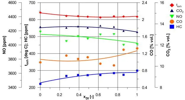
· The following Figure 16 shows recorded at a speed of 2000 RPM and a throttle opening of 20% traces of the temperature and the concentrations of the previously mentioned exhaust gas components.
IMPACT OF THE USE OF THE DUAL-INJECTION SYSTEM ON THE COMBUSTION PROCESS
In the second part of the experimental studies for engine speed 2000 RPM, throttle opening 20% and stoichiometric composition of the mixture the waveforms of an indicated pressure have been recorded. As in previously carried out studies in these conditions, ignition timing was 14° CA before TDC. The measured absolute pressure in the intake manifold equalled 0.079 MPa. The direct injection pressure was set at 8 MPa, and the angle of start of injection was 281° CA before TDC. The fraction of fuel injected directly into the cylinder in dual-injection mode was equal to 0.62. For such a value the minimum of specific fuel consumption for those conditions was recorded.
The tests were conducted to determine the differences in the combustion process in the engine for indirect fuel injection and for dual-injection with predetermined fraction of fuel injected directly into the cylinder providing minimum specific fuel consumption. An optoelectronic pressure sensor Optrand C82255-SP attached to a specially prepared spark plug and an angular incremental encoder Omron E6B-CWZ3E were used for this purpose. The data from both of the sensors were recorded using a portable PC with National Instruments DAQCard-6062 card working with the application created in LabView environment.
The indicator diagrams obtained for the operation with only indirect injection and using the dual-injection system were illustrated in Figure 17.
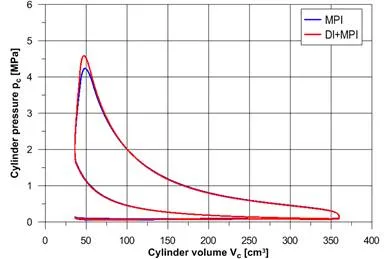
The increased surface area of the graph representing the positive work of the engine cycle is visible. The peak combustion pressure reached a value of 4.23 MPa at 21° CA after TDC with indirect injection and 4.60 MPa at 19.5° CA after TDC in the dual-injection mode. The peak combustion pressure with dual-injection is thus higher by the value of 0.37 MPa as compared with the result obtained for the injection only to the intake channels. In order to more precisely determine the differences resulting from the course of the indicator diagrams the indicated mean effective pressure IMEP was calculated based on the recorded data, respectively for the two cases. The method of numerical integration of relevant areas of the graphs of Figure 17 was applied. In order to provide increased accuracy trapezoid method was used.
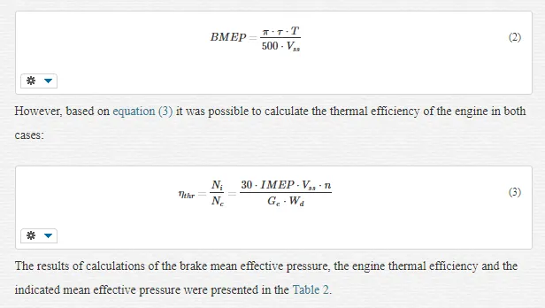
The brake mean effective pressure BMEP was determined according to the formula (2) for both considered fuel systems :
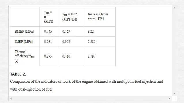 Using dual-injection system about 2.6% increase in the indicated mean effective pressure and about 3.8% increase in the thermal efficiency were achieved compared to injection only into intake channels. These values are similar to those obtained in the corresponding comparison made for the specific fuel consumption for the considered engine operating conditions. On this basis, it can be concluded that the increase in indicated mean effective pressure and thermal efficiency shows improved combustion efficiency of the mixture prepared by dual-injection system. This fact can be explained as reflected in the simulations intensifying turbulence of the charge when part of the fuel is injected directly into the cylinder.
The last indicator in this part of the analysis of the indicator diagrams is the rate of pressure rise dpc/dα. The curve of this parameter as a function of crank angle was shown in Figure 18 for the crucial part of the indicator diagram. The rate of pressure rise was adopted as the primary indicator of the possibility of occurring of the knock combustion.
· 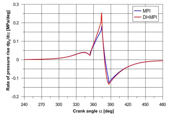 The analysis of the results indicates an increase of rate of pressure rise in the case of dual-injection of fuel. The peak rate of pressure rise amounted to 0.181 MPa/° CA for fuel injection into the intake channels and 0.253 MPa/° CA for dual-injection of fuel. The increase of the rate of pressure rise is not a favourable phenomenon, as it provides increased load in the cranktrain, however, the value obtained for the dual-injection system is not high. It is worth to mention that the occurrence of knock in a spark-ignition engine is characterized by occurring of peak rates of pressure rise typically higher than 0.5 MPa /° CA [14].
The second stage of the analysis of the cylinder pressure charts obtained for both of the fuel systems was focused on the identifying of the process of mixture combustion. The method of the analysis of indicator diagram allowing to determine the mass fraction burned (MFB) in the cylinder as a function of crank angle was applied. This method is widely described among others in [15].
Figure 19 shows the traces of the mass fraction burned as a function of crank angle obtained for both fuel systems. In the Figure 26, the ordinate grid lines corresponding to mass fraction burned in the cylinder of 0.1 and 0.9 are in bold. The mentioned values are important due to the combustion process.
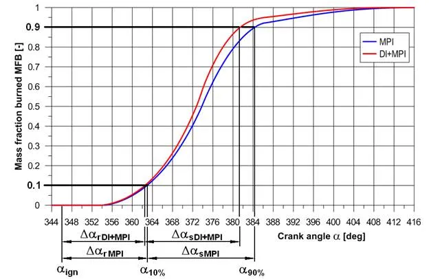
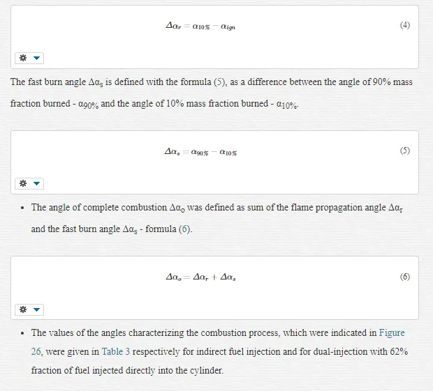
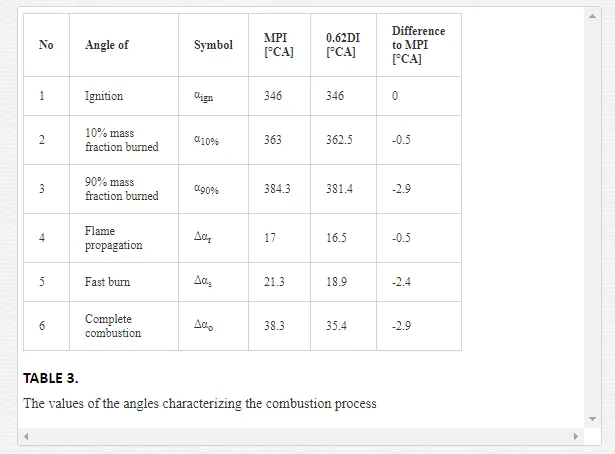
In the case of the dual-injection the angle of flame propagation was reduced from 17 to 16.5° CA, and, more importantly, the fast burn angle was decreased from 21.3 to 18.9° CA. The angle of complete combustion Δαo, which is the sum of the two above mentioned, has reached values, respectively 38.3° CA at indirect fuel injection and 35.4° CA for the dual-injection of fuel. This gives a reduction in the angle at which the most important part of the combustion process takes place of 2.9° CA i.e. about 7.6%. This is undoubtedly the reason for an increase in indicated mean effective pressure IMEP and thermal efficiency ηthr, which were analyzed above. The combustion of the mixture in a shorter time results lower heat losses occurring by the cylinder sleeve, because in this case a part of the cylinder sleeve in contact with a hot charge has a smaller surface area.
On the Figure 20 curves of speed of the charge combustion dMFB/dα as a function of crank angle were shown for the two fuel systems. The speed of the charge combustion was obtained by differentiating the mass fraction burned MFB shown in Figure 19 relative to crank angle.
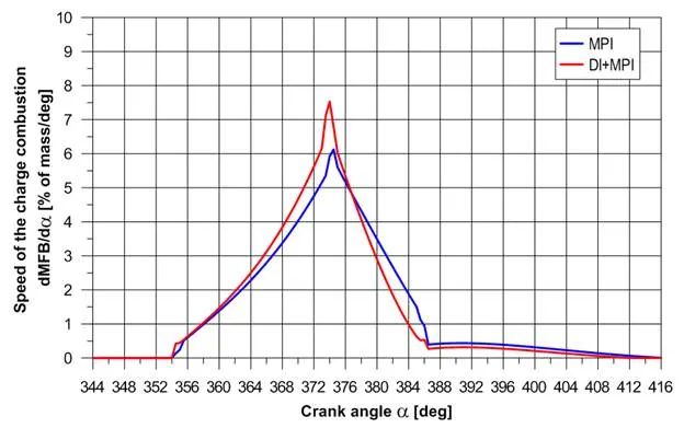
The speed of the charge combustion in the most part of the period of fast burn achieved higher values of average 0.54% mass of the burned charge per 1° CA for dual-injection of fuel. The absolute difference in the speed of charge combustion obtained with dual-injection of fuel reaches a maximum value of 1.76% of the mass per 1° CA at 373.5° CA. In the second part of the period a fast burn with indirect fuel injection the process runs more intense, but the greatest effect on improving the thermal efficiency of the engine has increasing of the speed of the charge combustion in the first stage of the process, i.e. to reaching of 50% mass fraction burned [16].
Therefore, the above considerations represent a confirmation of the positive impact of using of the dual-injection system on the combustion process for the assumed engine operating conditions. The result of this interaction is improvement of the engine operation indicators, such as, among others Indicated mean effective pressure IMEP and thermal efficiency ηthr, which values have a direct impact on the total efficiency of the engine ηtot.
KIVA-3V simulations of work of the test engine 2SZ-FE
The carried out simulations were focused on the determination and comparison of the differences in the combustion process in the cylinders of the engine working with the port- and dual-injection of fuel in conditions similar to occurring at experimental research.
In order to determination of the phenomena occurring in the cylinder, computer simulations were performed in programme KIVA-3V. Used for three-dimensional modelling of processes in internal combustion engines KIVA-3V program takes into account the physical and chemical phenomena that occur during forming of the mixture and its combustion [17,18]. The programme takes into account movement of fuel droplets and their atomization in the air using a stochastic model of the injection.
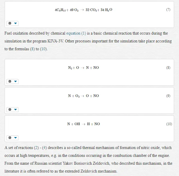
KIVA-3V has the ability to simulate the engine operation using different fuels. In the described work a hydrocarbon with the chemical formula C8H17 was used as the fuel. One can see similarities to octane (C8H18), however, this substance have more comparable proportions of carbon and hydrogen in the molecule to the petrol than octane. Therefore, it can be regarded as a special kind of single-component petrol. The C8H17 fuel is oxidized according to the reaction (7).
Preparations for simulations have included a generation of a mesh of one of the engine’s cylinder and modifying the source code of KIVA-3V in order enable the simulation of work with both of the fuel injectors at the same time, what in the basic version of the program is not possible. The computational mesh was built based on the results of previous positively verified solutions in that matter. The grid consists of a cylinder 35 of horizontal layers. 21 layers of equal thickness falls to 81% of piston stroke starting from the bottom dead centre. The remaining 14 layers around the top dead centre was concentrated to obtain more advantageous terms of the simulation of combustion process that takes place there (combustion chamber). The cylinder mesh has transverse-sectional dimensions respectively 38 x 34. It gives together around 45000 cells in the whole cylinder volume.
Used in the research an engine model was developed based on available technical data of 2SZ-FE engine. Dimensions required to generate a grid, especially cylinder head and valves lift were obtained by direct measurement of elements of the modified engine.
INITIAL AND BOUNDARY CONDITIONS FOR SIMULATIONS
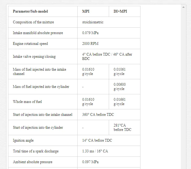
In both of the simulation, with indirect fuel injection and dual-injection of fuel in both simulations conditions, such as occurring during research which results were presented in Figure 14, were maintained. In the case of simulation of engine with dual-injection of fuel the whole amount of fuel was divided between indirect injection systems and direct, so that the fraction of direct injection xDI was 0.62. At this fraction the engine gained the best value of the total efficiency. List of crucial assumptions and sub-models used in the simulations were presented in Table 4, respectively for indirect- and dual-injection of fuel.
COMPARISON OF SELECTED SIMULATION RESULTS FOR BOTH OF THE FUEL SYSTEMS
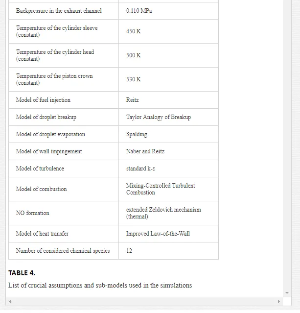
Figure 21 shows traces of pressure in the cylinder pc as a function of a cylinder volume in the case of indirect fuel injection and during work with the dual-injection system.
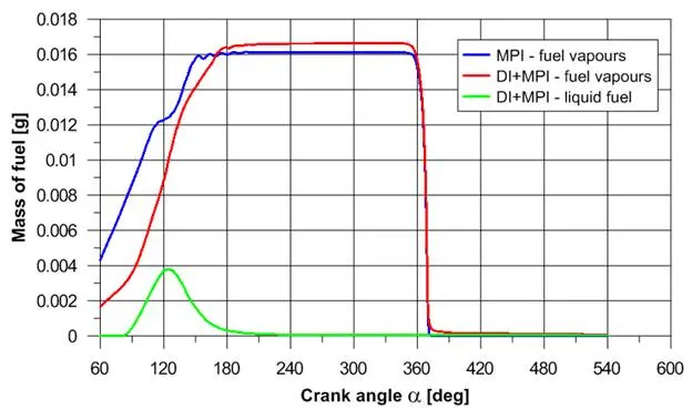 In the case of fuel injection only to the intake channel in the considered period of time in the cylinder exist only the fuel vapours. When the dual-injection system is used, the fuel injected directly into the cylinder evaporates completely before the moment of ignition. This fact is represented on the chart by achieving zero by the curve of the green (mass of liquid fuel) and the maximum of the curve of the blue (mass of fuel vapour), which takes place about 120° CA before TDC, while the ignition timing in the simulation was assumed at 14° CA.
The angular momentum of the charge Ktot is a indicator of the intensity of swirl and tumble turbulence in the cylinder, which affect the intensity of the evaporation of the fuel, its propagation within the cylinder volume, and consequently the speed of the flame spread. Traces of the total angular momentum of the cylinder charge were shown in Figure 23.
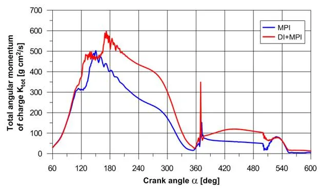 One can see the impact of fuel stream injected directly into the cylinder on charge. In the case of dual-injection of fuel the angular momentum in the intake and compression process achieves values greater than is the case of fuel injection only into intake channel. Intensification of the cylinder charge turbulence has undoubtedly an important influence on the improvement of the combustion process, and thus, to increase the torque of the engine.
On the Figure 24 mass fraction of hydrocarbons HC, carbon monoxide CO and nitrogen oxide NO in the cylinder were shown as a function of crank angle for indirect injection and for the dual-injection of fuel.
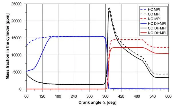
On the basis of analysis of the graphs contained in Figure 24 it can be concluded that there are some differences in the formation of carbon monoxide CO, hydrocarbons HC and nitrogen monoxide NO depending on the concerned injection system. After end of the combustion in the cylinder of the engine working with indirect fuel injection there is slightly more CO and NO than in the case when the amount of fuel divided between the two injection systems. When the fuel is injected by two injectors a fraction of unburned hydrocarbons is higher than with the indirect injection. The difference amounts to about 80 ppm, so it is not a significant disadvantage.
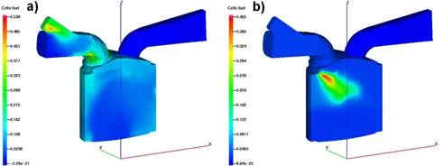
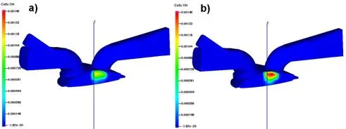
Figure 25 shows the distribution of the mass fraction of fuel in the longitudinal section of the cylinder in the intake stroke for the each considered fuel system.
SUMMARY OF THE SIMULATIONS RESULTS
The carried-out simulations of the engine working with fuel injection only into the intake manifold and dual-injection of fuel gave the following conclusions:
· Obtaining with the dual-injection of fuel the same mixture composition, which occurred with indirect injection, requires a slightly larger amount of fuel. This fact points to improve of volumetric efficiency for the engine working with dual-injection in those simulation conditions. The same effect was obtained during the experimental tests,
· The fuel injection into the cylinder during the intake stroke causes intensification of charge motion. The measure of this process is to increase the total angular momentum of the charge in the intake stroke. This advantageous phenomenon has a positive influence on the formation of combustible mixture and on the combustion.
· It was observed that with dual-injection the whole mass of the fuel evaporates 100° CA before the moment of ignition. The time taken to create as homogenous mixture as it is possible in this case, is therefore comparatively long. This fact explains the slightly increased emission of HC during work with dual-injection of fuel in experimental tests.
· For the dual-injection of fuel the combustion peak pressure is higher by about 6% compared to the value of the pressure obtained for the fuel injection only into the intake manifold. The average rate of the pressure rise dpc/dα from the moment of ignition to reach peak pressure at the dual-injection of fuel amounting to 0.16 MPa/° CA is slightly higher than is the case of port fuel injection – 0.15 MPa/° CA. The nature of these differences is quite similar to the results obtained on the test bench.
· The cycle of the engine with dual-injection of fuel is characterized by higher by about 3% of the value of the indicated mean effective pressure than for the engine with multipoint fuel injection. Increase of IMEP was also achieved in experiments.
In conclusion, the results obtained during the simulations were an important complement to the outcome of experimental tests.
Conclusions
On the basis of the results of carried out considerations the following conclusions can be presented:
· The outcome of computational part of the work are convergent with the experimental research results. This confirms the proper design of the model and indicates the possibility of its further use.
· With the dual-injection fuel system in the analyzed operating conditions of the engine a few percent increase in total efficiency was obtained, what in the present state of development of the internal combustion engines is an important value. This fact clearly indicates the desirability of conducting research related to the taken issues.
· The analysis of indicator diagrams registered for work with indirect fuel injection and dual-injection of fuel revealed increase in the indicated mean effective pressure and improve engine thermal efficiency with dual-injection of fuel.
· There were no significant changes in the composition of the exhaust gas together with changing the fraction of fuel injected directly into the cylinders. In comparison with the values obtained for indirect fuel injection with the increase in the fraction of fuel injected directly into the cylinder occurs the reduction of nitric oxide concentration with a slight increase in the concentration of carbon monoxide and hydrocarbons.
· In view of the total efficiency the optimal value of fraction of fuel injected directly into the cylinder grows when increasing the engine load at specified rotational speed,