
You are approaching a roundabout in an electric vehicle. Your foot presses the brake pedal, the car slows smoothly, and the battery quietly receives energy that would once have become heat at the brake discs. To the driver, it feels like one simple action.
Behind that familiar pedal movement, however, several systems may be making decisions in milliseconds. The vehicle must judge how much deceleration the driver wants, how much can safely come from the electric motor, whether the tyres have enough grip, and whether friction brakes must contribute.
This coordination matters because braking is a safety-critical function, while regenerative braking is also an efficiency opportunity. Brake-by-wire technology is the control architecture that can bring those goals together without asking the driver to manage them separately.
The result is not merely a car that recovers energy. At its best, it is a vehicle that delivers predictable pedal feel, stable stopping behaviour, and the maximum practical energy recovery under changing conditions.
🚗 The Simple View of a Complex Brake Event
Conventional braking has a direct mechanical and hydraulic chain: pedal force operates a booster and master cylinder, hydraulic pressure travels through brake lines, and calipers squeeze pads against rotating discs.
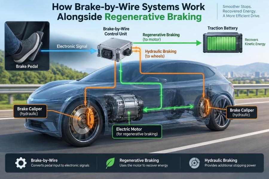
In a brake-by-wire system, the driver still presses a pedal, but electronics take a larger role in interpreting that request. Sensors, control units, electric actuators, and hydraulic components work together to produce the requested braking torque.
The pedal request and the wheel-braking method can be partly decoupled. That decoupling is what makes precise blending with regenerative braking possible.
⚡ What Regenerative Braking Actually Does
An electric traction motor normally converts electrical energy from the battery into wheel torque. During regeneration, the energy flow reverses: the driven wheels turn the motor, and the motor operates as a generator.
The generator resists rotation, creating braking torque. The recovered electrical energy passes through power electronics and is sent back to the high-voltage battery, subject to the battery management system’s limits.
Regeneration cannot replace friction braking in every situation. Its available torque depends on motor speed, battery condition, temperature, traction, and the capabilities of the vehicle’s electrical system.
🧲 From Kinetic Energy to Electrical Energy
A moving vehicle has kinetic energy. Conventional disc brakes reduce that energy mainly by converting it into heat through friction between pads and discs.
Regenerative braking redirects part of the same energy path. Rather than dissipating all of it as heat, the motor-generator converts some of it into electricity. Conversion is not lossless: motors, inverters, cables, and batteries all produce losses.
Even so, recovery can be useful, particularly where repeated slowing is required. Urban traffic, rolling terrain, and controlled descents often create more opportunities than steady motorway cruising.
🦶 Why the Brake Pedal Cannot Be a Simple Switch
Drivers expect pedal travel and pedal force to correspond predictably to deceleration. They also expect that relationship to remain stable whether the battery is warm, cold, nearly full, or unable to accept much charge.
A brake-by-wire controller receives pedal-travel and force information, then calculates a target deceleration or total wheel-braking torque. It allocates that demand between regenerative and friction braking.
If regenerative capacity changes suddenly, friction braking must fill the gap without a noticeable delay or step in deceleration. This is called brake blending, and it is central to a refined electrified vehicle.
🧠 The Brake Control Unit as Coordinator
The brake control unit is the system coordinator. It combines inputs from pedal sensors, wheel-speed sensors, vehicle-motion sensors, motor controllers, the battery management system, and stability-control functions.
It does not simply ask, “Can the motor regenerate?” It also asks whether regeneration at this axle will preserve stability, whether a wheel is close to locking, and whether the desired deceleration can be achieved comfortably and safely.
Its output may command hydraulic pressure at individual wheels, request negative torque from one or more electric machines, operate valves, or control an electrically driven pressure source.
📡 Sensors That Turn Driver Intent into Data
Pedal-position sensors measure how far the pedal moves. Many designs use redundant sensor channels so the controller can compare signals and identify implausible readings.
Other useful inputs include pedal force, master-cylinder pressure, wheel speeds, steering angle, yaw rate, longitudinal acceleration, motor speed, and battery temperature. No single signal tells the whole story.
For example, rapid pedal application combined with high pedal force may be interpreted as an urgent braking demand. A gentle pedal application on a dry, straight road allows much more freedom to prioritise energy recovery.
🔌 The Role of the Inverter and Traction Motor
The inverter controls the electrical currents in the traction motor. During propulsion it produces motor torque; during regeneration it controls generator torque.
Generator torque has to be carefully managed because it acts through the driven wheels. Excessive negative torque can reduce tyre grip at those wheels, especially on a wet, icy, or uneven surface.
The motor also has a speed-dependent operating range. At very low vehicle speeds, it may not generate useful braking torque, so friction brakes usually complete the final stop.
🔋 Why Battery Acceptance Limits Matter
A battery can accept charge only within operating limits set to protect its cells and preserve performance. A battery near its upper state of charge may accept little or no regenerative energy.
Low temperatures can also reduce charge acceptance. In those conditions, the car may rely more heavily on friction brakes even though the driver uses the same pedal input as usual.
This is a practical reason pedal feel must not directly reveal regenerative availability. The vehicle must deliver the commanded stopping response even when energy recovery is limited.
🌡️ Temperature Changes the Braking Mix
Battery temperature influences regeneration, but it is not the only thermal factor. Motor, inverter, and brake temperatures can also affect the preferred torque split.
On a long descent, a battery may reach a charge limit or components may approach thermal limits. The controller then reduces regeneration and increases friction braking as required.
Friction brakes themselves can heat significantly during sustained high-energy braking. Vehicle systems and driver guidance must therefore never treat regenerative braking as an unlimited substitute for conventional braking on steep or prolonged descents.
🛞 Tyre Grip Sets the Ultimate Limit
The tyre-road contact patch is the final authority in any braking event. If requested braking torque exceeds available grip, a wheel can begin to slip or lock regardless of whether torque came from a motor or a hydraulic caliper.
Anti-lock braking system (ABS) control monitors wheel behaviour and modulates brake torque to maintain steerability. Electronic stability control can also alter individual wheel braking to help manage yaw stability.
Regeneration must cooperate with these systems. When wheel-slip control is active, regenerative torque may be reduced quickly so hydraulic control can manage each wheel precisely.
⚖️ Brake Blending: Sharing the Deceleration Demand
Brake blending means combining regenerative and friction braking so their total effect matches the driver’s requested deceleration. It is a continuous control problem, not a fixed percentage split.
Consider a hypothetical gentle approach to a traffic light. The controller may obtain most of the demanded torque from the motor and apply little or no friction pressure. If the driver then brakes harder, hydraulic braking rises as motor regeneration reaches its usable limit.
For the driver, the desired outcome is linearity: more pedal demand should mean more deceleration, not an unexpected change in response when the torque source changes.
🔄 Series and Parallel Brake Blending
Control strategies are often described as series or parallel blending. In a series approach, regenerative braking is used first where possible, with friction braking added when needed to meet the remaining demand.
In a parallel approach, regenerative and friction braking can act together across a wider operating range. The exact implementation varies with the vehicle architecture, brake hardware, and calibration goals.
| Approach | General characteristic | Control challenge |
|---|---|---|
| Series blending | Regeneration is prioritised before friction braking contributes substantially. | Avoiding a noticeable transition when friction braking joins. |
| Parallel blending | Both torque sources may contribute at the same time. | Accurately coordinating total torque and pedal feel. |
Neither label alone tells you how refined a vehicle feels. Calibration, actuator response, sensor quality, and safety strategy matter just as much.
🧩 How Pedal Feel Is Created
In a conventional system, pedal feel arises largely from hydraulic pressure, hose expansion, seal movement, pad contact, and the brake booster. Brake-by-wire can partially separate pedal feel from actual wheel pressure.
A pedal simulator may use springs, dampers, and sometimes controllable mechanisms to provide a natural resistance curve. The driver feels a deliberate, engineered pedal response while the controller manages braking torque elsewhere.
This arrangement can make pedal feel more consistent when regeneration changes. It also demands careful design: artificial or inconsistent feedback can make drivers lose confidence in the system.
💧 Hydraulic Brakes Remain Essential
Brake-by-wire does not mean that hydraulic friction brakes disappear. Passenger vehicles still require friction brakes for low-speed stopping, emergency braking, parking-related functions in many designs, and situations where regeneration is unavailable.
Hydraulic braking also provides high braking force independent of battery charge acceptance. Discs, pads, calipers, brake fluid, lines, and pressure-generating components remain important maintenance and safety items.
The key change is that electronic control can decide how and when hydraulic pressure is generated, distributed, and blended with motor braking.
🛑 Emergency Braking Prioritises Stopping Performance
During a severe braking event, recovering energy becomes secondary. The controller aims to achieve maximum stable deceleration within tyre-grip and vehicle-dynamics limits.
Regeneration may still contribute if it is predictable and compatible with ABS and stability control. But it can be reduced or cancelled whenever that gives the wheel-slip controller faster, more reliable authority.
This is an essential design principle: efficiency functions must yield to braking safety and directional control.
🌧️ Low-Grip Roads and Stability Control
On a slippery road, abrupt regenerative torque at the driven axle can influence vehicle balance. In a rear-wheel-drive electric car, strong lift-off regeneration can add rear-axle braking and may require careful stability management.
Wheel-speed differences, yaw-rate sensors, steering angle, and estimated road friction help the controller identify developing instability. It can reduce regeneration, apply individual hydraulic brakes, or both.
Drivers should not assume that a strong one-pedal deceleration setting will behave identically on every surface. Well-designed systems adapt, but the available grip still determines how rapidly the vehicle can slow.
⬇️ The Final Metres Before a Stop
As vehicle speed falls, motor-generator braking generally becomes less effective. At very low speed, the controller transitions to friction braking to stop the vehicle smoothly and hold it stationary.
A poorly calibrated transition can feel like a small surge, a release-and-grab sensation, or an inconsistent final stop. Engineers spend considerable effort tuning this region because drivers notice it immediately in traffic and parking manoeuvres.
Automatic hold functions can then maintain hydraulic braking after the vehicle reaches zero speed, reducing the need for the driver to keep pressing the pedal.
🚦 One-Pedal Driving Is Related but Not Identical
One-pedal driving increases deceleration when the driver releases the accelerator. It commonly uses regenerative braking first and may add friction braking under certain conditions, depending on the design.
It is not the same as pressing the brake pedal. Brake-pedal operation must handle a broader range of demands, including precise low-speed control and emergency stops.
Both functions benefit from coordinated control, but one-pedal driving is primarily an accelerator-lift strategy, whereas brake blending responds to an explicit braking request.
🔧 Common Brake-by-Wire Hardware Arrangements
Architectures differ. Some systems retain a conventional hydraulic path that is electronically assisted or controlled. Others use an integrated brake control unit containing pressure generation, valves, and electronic control in a compact assembly.
An electro-hydraulic brake system may use an electric motor to generate hydraulic pressure rather than relying mainly on an engine-driven vacuum source. This suits electric vehicles, which do not have a running combustion engine to provide manifold vacuum.
More advanced concepts can further separate pedal mechanics from wheel braking, but all road-going designs require robust fallback behaviour and fault monitoring.
🛡️ Redundancy and Fail-Operational Thinking
Because braking is safety-critical, brake-by-wire systems use multiple layers of protection. These may include redundant sensors, independent electrical supply paths, plausibility checks, hydraulic fallback paths, and diagnostic monitoring.
“Fail-safe” does not mean every possible failure leaves the vehicle operating normally. It means the system is designed to move to a defined safe state, often with reduced functionality, while retaining sufficient braking capability for the driver to stop.
The precise fallback method depends on the design. For that reason, service procedures and warning messages must be taken seriously rather than treated as ordinary electronic inconveniences.
🔍 Fault Detection and Warning Strategy
The controller continuously compares expected and measured conditions. If pedal sensors disagree, pressure fails to build as commanded, communication is lost, or an actuator behaves unexpectedly, a diagnostic fault can be recorded.
A warning may indicate that regenerative braking is unavailable, that brake assist is limited, or that a more urgent braking fault exists. These messages do not all mean the same thing.
If a brake warning remains illuminated, the correct response is to consult the vehicle manual and arrange qualified inspection promptly. A driver should never attempt to diagnose high-voltage or brake-control hardware by disconnecting components.
🧰 Maintenance Changes, but It Does Not Vanish
Regeneration can reduce routine friction-brake use, especially in city driving. That may slow pad wear, but it can also leave discs and caliper sliding parts exposed to corrosion or sticking because they operate less often.
Brake fluid still ages and may require replacement according to the manufacturer’s schedule. Tyres, suspension joints, wheel bearings, and wheel-speed sensor wiring also remain central to braking performance.
- Use the specified brake fluid and approved service process.
- Do not assume low pad wear means the brake system needs no inspection.
- Have warning lights, unusual pedal feel, pulling, vibration, or grinding checked by trained technicians.
- Follow vehicle-specific procedures before any work near high-voltage components.
🧪 Why Brake Servicing Requires Vehicle-Specific Procedures
On some brake-by-wire vehicles, service mode is needed before retracting calipers, bleeding circuits, or replacing pads. The system may otherwise attempt to generate pressure or move an actuator unexpectedly.
Electronic parking brakes, integrated hydraulic control units, and diagnostic routines add further differences from older mechanical systems. Generic habits can cause damage or leave air trapped in a system.
For working technicians, the lesson is straightforward: obtain the correct manufacturer procedure, use suitable diagnostic equipment where required, and verify brake operation after service.
📉 Efficiency Benefits in Real Driving
Regenerative braking is most useful when the vehicle repeatedly slows from moderate speeds. It can reduce energy wasted as brake heat and may lower friction-brake wear.
Its benefit is naturally limited during journeys with little braking, when the battery cannot accept charge, or when traction and stability demands restrict motor braking. It also cannot recover all energy used to accelerate the vehicle.
Efficient driving still matters. Looking ahead, easing off the accelerator early, and avoiding unnecessary speed changes reduce energy demand before regeneration is even considered.
⚠️ Misconceptions About Regeneration
One common misconception is that regenerative braking always charges the battery whenever the car slows. In reality, the system may limit or disable recovery because of battery state, temperature, traction control, component limits, or low speed.
Another is that high regeneration makes friction brakes unnecessary. Friction brakes remain indispensable for safety, for complete stops, and for braking demands beyond the motor’s available negative torque.
A third misconception is that energy recovery makes downhill driving risk-free. A long descent can still demand careful speed control and can still heat friction brakes if the battery cannot accept energy.
🏁 Differences Between Hybrid and Battery-Electric Vehicles
Both hybrids and battery-electric vehicles can blend regenerative and friction braking, but their hardware and priorities differ. A hybrid may have a smaller battery and an engine-related transmission arrangement that affects available regeneration.
A battery-electric vehicle often has a larger traction battery and may use one or more motors, potentially allowing regenerative torque at different axles. That can expand control options, but it also makes torque coordination more complex.
Vehicle layout matters more than the badge. Two electrified vehicles can feel quite different at the pedal even when both are described as having regenerative braking.
🧭 Calibration Is Where Engineering Meets Driver Confidence
Hardware provides capability; calibration determines how that capability feels. Engineers tune pedal maps, torque ramps, low-speed transitions, ABS interaction, and responses to changes in battery acceptance.
The aim is not necessarily to maximise regeneration at every instant. An aggressive recovery strategy that creates inconsistent pedal response, driveline jolts, or awkward vehicle balance may be a poor overall design.
A good system is often unobtrusive. The driver simply experiences stable, proportional braking while the vehicle recovers energy whenever conditions permit.
👨🔧 Practical Driving Habits for Better Results
Drivers do not need to calculate motor torque or battery charge limits. They can help the system by driving smoothly and leaving enough space to decelerate progressively.
- Anticipate traffic flow instead of braking late and hard.
- Use the selected regeneration mode consistently until its response becomes familiar.
- Expect reduced regeneration with a full or very cold battery.
- On steep descents, control speed early and do not rely on regeneration alone.
- In rain, snow, or loose gravel, leave greater following distance regardless of the selected driving mode.
These habits improve both energy recovery opportunities and the driver’s margin for safe braking.
🧱 Limits That Engineering Cannot Remove
Brake-by-wire control can react quickly and coordinate systems intelligently, but it cannot create grip where the road offers none. Nor can it make a battery accept charge outside its safe operating limits.
Vehicle mass, downhill gradient, tyre condition, road surface, brake temperature, and driver reaction remain real constraints. Advanced controls manage these constraints; they do not eliminate them.
Understanding those limits prevents misplaced confidence and helps explain why the car’s regenerative response may change from one journey to the next.
🔮 Where Brake Control Is Heading
Electrification, automated driving features, and multi-motor powertrains are increasing the value of precise, electronically coordinated braking. Future systems may integrate wheel torque, stability control, predictive route information, and energy management even more closely.
Yet the engineering priorities remain familiar: reliable deceleration, stable vehicle behaviour, clear driver feedback, fault tolerance, and serviceability. New control strategies must still meet the practical realities of tyres, hydraulics, batteries, and human expectations.
✅ The Core Principle: Safety First, Recovery Second
Brake-by-wire makes regenerative braking feel natural because it converts one pedal request into a carefully managed combination of motor braking and friction braking. It continuously adapts that combination to speed, grip, battery acceptance, component temperature, and vehicle stability.
The cleverness is not that a vehicle can recover energy while slowing. The real achievement is delivering predictable braking even when recovery is reduced, unavailable, or unsafe to use.
For students, this is a valuable systems-engineering example: mechanical, hydraulic, electrical, electronic, thermal, and control disciplines must work as one. For drivers and technicians, it explains why correct operation, maintenance, and fault response remain essential.
Brake-by-wire and regenerative braking succeed when the vehicle treats energy recovery as an opportunity, while always treating controlled stopping as the non-negotiable requirement. ⚙️🔋🛞