
You turn into a wet roundabout, add a little throttle, and the vehicle follows the curve with surprising calm. Or you accelerate out of a tight bend and notice that the car feels as though it is being guided around the corner rather than pushed wide toward the outside lane.
That sensation is not always down to tyre grip, a stiff suspension, or a talented driver. In many modern vehicles, software and hardware are actively deciding how much drive torque each wheel should receive—sometimes many times per second.
This capability is called torque vectoring. It is used in performance cars, all-wheel-drive crossovers, hybrids, and electric vehicles, where independently controlled motors make the idea especially powerful.
Understanding it reveals an important engineering truth: controlling total engine or motor output is only part of the job. Equally important is controlling where that force reaches the road.
🧭 What Torque Vectoring Means
Torque vectoring is the deliberate distribution of driving or braking torque between wheels to influence a vehicle’s motion. “Torque” is the twisting force delivered through a drivetrain, while “vectoring” means directing its effect to create a desired turning or stabilising response.
A system may send more positive drive torque to one wheel, reduce torque at another, or apply a small braking force at a selected wheel. The aim is not simply maximum acceleration. It is to manage yaw, the vehicle’s rotation about its vertical axis, while preserving usable tyre grip.
🔩 Torque Is Not the Same as Power
Torque and power are related but different. Torque is the twisting effort at a shaft; power describes how quickly work is being done. At the wheel, torque combines with tyre radius to create a longitudinal contact-patch force that propels or decelerates the vehicle.
For cornering control, the key question is often not “How much power does the vehicle make?” but “Which wheel receives how much wheel torque at this instant?” A modest torque difference across an axle can create a useful turning moment.
🛞 The Four Contact Patches Matter Most
Every steering, braking, and traction decision ultimately reaches the road through four small tyre contact patches. Each tyre has limited grip, and that grip must be shared among accelerating, braking, and cornering forces.
Engineers often describe this with the friction circle, although the real limit is not perfectly circular. If a tyre is already using most of its available grip to accelerate, less remains for lateral cornering force. Torque vectoring tries to use the available grip more intelligently rather than assuming it is unlimited.
↩️ Why Unequal Wheel Torque Can Turn a Vehicle
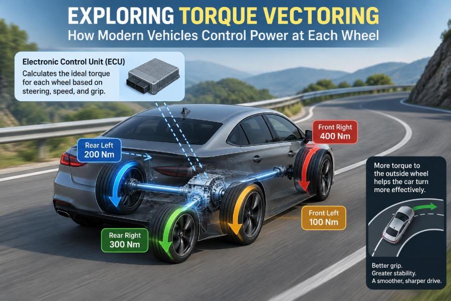
Consider the rear axle while a car is cornering right. If the outside rear wheel receives more drive torque than the inside rear wheel, it generates a larger forward force. Because that force acts farther from the vehicle’s centreline, it creates a yaw moment that helps rotate the car into the right-hand turn.
This is the central physical idea. A left-to-right difference in longitudinal tyre force produces a turning effect, much as unequal thrust can turn a boat. The vehicle is not being pulled sideways; it is rotating because forces at opposite sides of the vehicle are deliberately unbalanced.
📐 Yaw Rate: The Motion Controllers Watch
Yaw rate is how quickly a vehicle rotates left or right around its vertical axis. A yaw-rate sensor, commonly shared with electronic stability control, lets the control system compare actual rotation with the rotation expected from steering angle, speed, and vehicle behaviour.
If the actual yaw rate is too low for the driver’s steering request, the vehicle may be understeering. If it is too high, it may be oversteering. Torque vectoring can assist the response, but it must work within the grip available at the tyres.
📉 Understeer and the Driver’s Experience
Understeer occurs when the front tyres cannot generate enough lateral force for the chosen path. The vehicle turns less than the driver intends and tends to run wider in the bend. It can arise from excessive entry speed, heavy front loading, early throttle application, or low-grip pavement.
Rear-axle torque vectoring can reduce the tendency by creating an additional yaw moment into the corner. It cannot repeal physics: if the front tyres have very little grip on ice, for example, no reasonable torque split will make the vehicle corner sharply.
⚠️ Oversteer Requires a Different Priority
Oversteer occurs when the rear of the vehicle rotates more than intended. A performance-oriented system may allow a small, controlled degree of rotation in selected modes, but safety-focused calibration usually seeks to prevent a developing spin.
In that condition, a controller can reduce rear drive torque, alter the front-to-rear split in an all-wheel-drive system, or coordinate with stability control braking. The best action depends on vehicle layout, surface friction, driver demand, and how quickly the motion is changing.
🧠 Torque Vectoring Is a Closed-Loop Control Problem
A modern system does not merely follow a fixed torque map. It measures vehicle state, estimates tyre capability, calculates a target yaw response, and commands actuators. The result is checked again through sensor feedback.
Inputs commonly include steering-wheel angle, wheel speeds, yaw rate, lateral and longitudinal acceleration, throttle position, brake demand, gear selection, and motor or engine state. Some systems also use road-surface estimates derived from wheel slip and other vehicle signals.
📡 Sensors Provide the System’s Awareness
Wheel-speed sensors reveal whether one wheel is rotating unusually quickly, a possible sign of slip. The steering-angle sensor indicates the driver’s requested path, while the inertial measurement sensors show what the vehicle is actually doing.
No sensor directly measures every contact-patch force in ordinary production vehicles. Controllers therefore rely on models and estimates. This is one reason calibration matters: noisy signals, changing tyres, uneven roads, and rapidly changing friction all introduce uncertainty.
⚙️ Open Differentials Explain the Original Problem
A conventional open differential allows left and right wheels on an axle to rotate at different speeds, which is essential in a corner because the outside wheel travels farther. However, it tends to send similar torque to both axle shafts.
Its practical traction limit is set by the wheel with less available grip. If one wheel is on ice and the other is on dry pavement, the low-grip wheel can spin while the high-grip wheel receives too little torque to move the vehicle effectively.
🔒 Limited-Slip Differentials Offer a Mechanical Solution
A limited-slip differential, or LSD, resists excessive speed difference between axle shafts. Clutch-pack, helical-gear, and viscous designs can transfer more usable torque toward the wheel with better traction than an open differential can.
An LSD improves traction and can influence handling, but it does not necessarily choose a wheel-by-wheel torque split based on steering angle and yaw feedback. Its behaviour is often governed by mechanical properties, preload, locking characteristics, and applied torque.
🧲 Active Differentials Add Electronic Authority
An active differential typically uses electronically controlled clutches or other actuators to vary how strongly the axle shafts are coupled. It can change locking action according to driving conditions rather than relying only on fixed mechanical behaviour.
Some active units can produce a meaningful side-to-side torque bias; others mainly control coupling and traction. The label torque vectoring is used broadly in marketing, so engineers should examine the hardware and control strategy rather than assume identical capability.
🛑 Brake-Based Torque Vectoring Uses Existing Hardware
Brake-based torque vectoring applies the brake lightly to an inside wheel during cornering. Braking that wheel produces a yaw moment toward the corner, helping the vehicle rotate. Electronic stability control hardware makes this approach comparatively accessible.
It is effective for transient handling support and can imitate some benefits of a torque-vectoring differential. Its main drawback is energy loss: braking turns kinetic energy into heat, and the engine or motor may need to provide additional drive force to maintain speed.
🔥 Why Brake Heat Limits Repeated Use
On a normal road, torque-vectoring brake interventions are usually brief. During repeated hard cornering, however, a brake-based system can add thermal load to a caliper, disc, and pad already working hard from driver braking.
When brake temperatures rise excessively, friction characteristics can change and brake fade becomes a concern. Manufacturers manage this with control limits and thermal models, but a dedicated active differential or electric motor system can be more efficient for sustained performance driving.
🔄 Torque Transfer Versus Torque Reduction
These terms are often confused. A brake-based system typically reduces torque at one wheel by braking it; it does not physically transfer that energy to the opposite wheel. An active differential can redistribute some driveline torque, though losses remain.
An electric axle with separate motors can independently command torque at each side, within motor and battery limits. This distinction affects efficiency, thermal performance, and the size of the handling effect the system can produce.
🚙 Front-to-Rear Torque Distribution Is Different
Many all-wheel-drive systems vary torque between the front and rear axles. This can improve launch traction, stability, and balance, but it is not automatically left-to-right torque vectoring.
A vehicle may have front-to-rear coupling only, side-to-side vectoring only on one axle, or both. For example, moving more drive rearward may change handling balance, while a rear side-to-side torque difference directly creates a yaw moment.
🧩 Common Torque-Vectoring Architectures
| Architecture | Primary method | Useful strength | Main limitation |
|---|---|---|---|
| Brake-based system | Brakes a selected wheel | Uses existing ESC components | Creates heat and wastes energy |
| Active differential | Clutches or gearing bias axle torque | Strong, repeatable axle control | Mechanical complexity and mass |
| Dual-motor electric axle | Independent motor torque commands | Fast, efficient positive/negative torque control | Cost, thermal and battery constraints |
| Four-motor vehicle | One motor per wheel | Maximum control freedom | Coordination and packaging challenges |
Real vehicles may combine these methods. A controller can use motor torque first, then request braking only when additional stabilising authority is needed.
⚡ Electric Vehicles Change the Opportunity
Electric motors can adjust torque rapidly and accurately, without engine air-path delays or gearshift interruptions. With one motor per axle, an EV can control front-to-rear distribution; with separate motors on an axle, it can also create direct side-to-side torque differences.
Regenerative braking expands the options. During deceleration, one motor may recover energy while helping generate a stabilising yaw moment. Yet regenerative capability varies with battery state, battery temperature, motor speed, and traction, so friction brakes remain essential.
🔋 Negative Torque Is Part of the Picture
Torque vectoring is not limited to acceleration. Motors can apply negative torque during regeneration, resisting wheel rotation and converting some vehicle kinetic energy into electrical energy.
For instance, in a carefully managed electric vehicle, different regenerative torque at the left and right wheels can contribute to corner entry balance. The controller must ensure the commanded deceleration does not exceed available tyre grip or conflict with the driver’s braking request.
🏎️ Corner Exit Shows the Benefit Clearly
Imagine a hypothetical all-wheel-drive vehicle leaving a medium-speed right-hand bend. The driver increases accelerator demand as the steering begins to unwind. The outside tyres carry more vertical load due to cornering, although load transfer does not increase total axle grip in a perfectly proportional way.
A capable system may direct more rear-axle drive torque to the outside wheel, while managing front-to-rear torque so the front tyres retain capacity to steer. The result can be cleaner acceleration and less need for abrupt stability-control intervention.
🌧️ Low-Friction Surfaces Need a Conservative Strategy
Snow, ice, gravel, wet leaves, and standing water reduce and vary available friction. On such surfaces, wheel torque changes that feel subtle on dry asphalt can provoke wheelspin or unwanted rotation.
Control software therefore needs mode-dependent limits and accurate slip management. The goal is generally stable, predictable progress rather than an aggressive yaw response. Good torque vectoring supports the driver; it should not create surprise.
🛻 SUVs Face Different Load-Transfer Demands
Tall, heavy vehicles can benefit from torque management, particularly during wet-road launches and lane changes. Their higher centre of gravity produces more load transfer in cornering, and their tyres may be tuned for comfort, all-season use, or off-road performance rather than maximum lateral grip.
Torque vectoring cannot eliminate rollover risk, overcome excessive speed, or replace electronic stability control. In these vehicles, calibration normally favours composure, traction, and gradual intervention over highly agile rotation.
🧪 Calibration Determines the Vehicle’s Character
Hardware provides capability; calibration decides how that capability feels. Two vehicles with similar active differentials may behave very differently because their controllers use different targets, filters, intervention thresholds, and driving-mode logic.
A comfort mode may minimise noticeable corrections. A sport mode may permit more yaw response before intervening. A track-oriented mode may assume a skilled driver and high-friction conditions, but it still operates within safeguards designed by the manufacturer.
🎛️ Driving Modes Do More Than Add Throttle Response
Selectable modes often change torque-vectoring behaviour along with accelerator mapping, damper settings, steering assistance, and stability-control thresholds. The names vary, but the underlying trade-off is between stability margin, agility, comfort, and thermal demand.
Drivers should not interpret a sport setting as extra tyre grip. It changes how available grip is used and how quickly the vehicle responds. Surface conditions remain more influential than a mode label.
🧱 Mechanical and Control-System Limits
Clutches have torque and temperature limits. Differentials require lubrication and robust gears. Motors have current, voltage, speed, and thermal limits. Batteries cannot always provide or accept the same power, especially when very cold, very hot, or near charge limits.
Controllers also have limits. They must avoid oscillatory corrections, respect actuator response delays, and remain stable when tyre friction estimates are imperfect. A well-designed system fades its requests gracefully when conditions prevent the ideal torque split.
🛞 Tyres Can Override Sophisticated Software
The best vectoring controller still depends on tyres with adequate tread, correct inflation pressure, suitable compound, and no structural damage. Mixed tyre types or severely unequal wear across an axle can change grip and rolling radius, complicating vehicle behaviour.
For road vehicles, fitting tyres that meet the manufacturer’s approved size and specification remains a practical foundation. Torque vectoring may help use grip effectively, but it cannot create adhesion where the tyre-road interface cannot provide it.
🔧 Maintenance and Warning Signs
Active differentials, transfer cases, and electric drive units may have specified service procedures, fluids, or inspection requirements. Ignoring these can affect durability and, in some designs, the consistency of torque-control performance.
A drivetrain warning lamp, unusual binding in tight turns, persistent tyre-size mismatch alerts, or abrupt stability-control activity deserves proper diagnosis. Fault codes alone do not identify the cause; technicians need to consider tyres, sensors, wiring, brakes, fluid condition, and mechanical components together.
🚫 Common Misunderstandings to Avoid
- “It gives unlimited cornering grip.” It only manages the grip available.
- “All AWD systems torque-vector.” Many distribute torque only between axles.
- “Braking one wheel is the same as transferring torque.” Both can influence yaw, but their energy paths differ.
- “It replaces skill or safe speed selection.” It assists control; it does not cancel inertia or road conditions.
- “More intervention is always better.” Excessive or poorly timed intervention can feel artificial, slow the vehicle, or add heat.
🧰 How Engineers Evaluate a System
Development involves simulation, proving-ground work, hardware-in-the-loop testing, and road validation. Engineers assess steady-state cornering, rapid lane changes, split-friction launches, brake-and-turn manoeuvres, rough surfaces, thermal endurance, and fault responses.
Subjective evaluation matters alongside measured data. A controller can meet a yaw-rate target yet feel abrupt if torque changes are poorly blended. The most successful systems produce a response that is predictable enough for ordinary drivers and informative enough for skilled drivers.
🛡️ Relationship With Electronic Stability Control
Torque vectoring and electronic stability control, or ESC, are closely related but not identical. ESC is primarily a safety system designed to help maintain directional control, commonly through individual wheel braking and engine or motor torque reduction.
Torque vectoring may pursue handling balance, traction, efficiency, or performance before a larger instability develops. In many vehicles, both functions share sensors and actuators, with safety-oriented stability control taking priority when necessary.
🧭 Choosing the Right Expectations as a Driver
When test-driving a vehicle, notice whether it tracks smoothly through a bend under gentle throttle and whether traction feels consistent when accelerating from a turn. These impressions depend on suspension, steering, tyres, weight distribution, and calibration—not torque vectoring alone.
On public roads, the useful benefit is usually confidence and predictability, not dramatic rotation. Keep steering inputs smooth, look well ahead, and leave a margin for changing surfaces. The system works best when the driver is not demanding more than the tyres can deliver.
🔮 Where Torque Vectoring Is Heading
Electrification gives designers finer control over wheel torque, while improved vehicle models and computing power enable more integrated control of motors, brakes, steering, and suspension. Four-motor architectures offer particularly broad possibilities because each wheel can be commanded separately.
Greater capability also makes validation more demanding. Engineers must ensure that torque commands remain understandable, robust to faults, and consistent across changing temperatures, tyre conditions, battery states, and road surfaces. More control authority requires more careful coordination.
✅ The Core Principle: Put Force Where It Helps Most
Torque vectoring is best understood as force management. By changing wheel torque distribution, a vehicle can create a helpful yaw moment, improve traction utilisation, and reduce the gap between driver intent and actual path.
Its effectiveness depends on the architecture: brake-based systems trade energy for control, active differentials add mechanical authority, and independently driven electric wheels offer exceptional flexibility. None of them changes the fundamental limits imposed by tyre grip, load transfer, vehicle mass, and road conditions.
Modern torque vectoring does not defeat physics; it applies physics more precisely at each wheel. For engineers, that makes it a compelling meeting point of drivetrain design, vehicle dynamics, sensors, software, and real-world safety. 🚗⚙️🛞