
A driver plugs in an electric vehicle after a long motorway trip, leaves it charging overnight, and expects it to be ready in the morning. Behind that simple routine, hundreds or thousands of battery cells must be charged, monitored, cooled, and kept within safe electrical limits.
Those cells do not all behave identically. One may be slightly warmer, another may hold a little less charge, and a third may age faster because of its position inside the pack. If the vehicle treated every cell as though it were exactly the same, battery performance and durability would suffer.
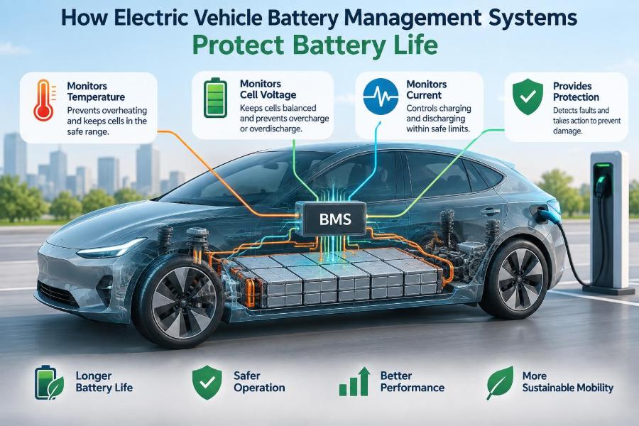
The component that prevents this is the battery management system, usually called the BMS. It is the battery pack’s measurement, decision-making, and protection system.
For automobile engineers, understanding the BMS is essential because battery life is not protected by a single switch or sensor. It is protected through continuous control of voltage, current, temperature, charging, balancing, diagnostics, and communication. ⚡
🔋 1. What a Battery Management System Is
A BMS is an electronic control system that supervises a rechargeable battery pack. In an EV, it gathers information from cells and sensors, estimates battery condition, and commands actions that keep operation within acceptable limits.
It does not create energy or repair degraded cells. Instead, it reduces avoidable stress and prevents conditions that can cause accelerated aging, poor performance, or safety risks.
🧩 2. Why an EV Pack Needs More Than a Simple Controller
An EV traction battery is built from many electrochemical cells connected in series, parallel, or both. Series connections raise pack voltage, while parallel connections increase current capability and energy capacity.
A problem in one cell group can influence the usable performance of the entire pack. The BMS therefore monitors the battery at cell or module level rather than relying only on total pack voltage.
- Cell level: detects the earliest imbalance or abnormal voltage.
- Module level: groups cells into manageable physical and electrical units.
- Pack level: manages vehicle power, contactors, insulation, and external interfaces.
⚗️ 3. The Battery Chemistry Sets the Rules
The BMS strategy depends on battery chemistry. Lithium-ion EV batteries may use cathode materials such as nickel manganese cobalt oxide, nickel cobalt aluminium oxide, or lithium iron phosphate, each with different voltage characteristics and thermal behaviour.
The BMS must use limits appropriate to the fitted cells. A voltage threshold, temperature window, or state-of-charge model that works for one chemistry cannot automatically be transferred to another.
Battery engineers also account for the fact that a cell’s behaviour changes with age, temperature, current, and prior use.
📏 4. Measuring Cell Voltage
Cell voltage is one of the BMS’s most important inputs. It indicates whether a cell is approaching its allowable upper or lower operating limit and helps reveal imbalance between cells.
During charging, the BMS watches for cells nearing the upper voltage limit. During driving, it watches for cells nearing the lower limit, where further discharge could damage the cell or produce an unacceptable voltage drop.
Accurate measurement matters because the usable voltage range of a lithium-ion cell is limited. Small measurement errors can become important when a cell is close to a protection threshold.
🌡️ 5. Monitoring Temperature Across the Pack
Temperature strongly affects battery power, charging acceptance, internal resistance, and aging. A BMS receives data from temperature sensors positioned at selected cells, modules, coolant paths, connectors, and sometimes power electronics.
One sensor cannot describe the entire pack. Designers place sensors where high temperatures are most likely, such as areas with limited cooling, high current paths, or closely packed cells.
- Low temperatures can reduce available power and make rapid charging unsuitable.
- High temperatures can speed up degradation and require cooling action.
- Large temperature differences can make cells age at different rates.
⚡ 6. Tracking Current and Power Flow
The BMS measures pack current during acceleration, regenerative braking, AC charging, and DC fast charging. Current data shows how quickly charge is entering or leaving the battery.
From voltage and current, the system can estimate electrical power. It uses this information to calculate safe charge and discharge limits for the vehicle control system and charging equipment.
High current is not automatically harmful, but its effects depend on temperature, cell condition, state of charge, and duration. The BMS turns these interacting factors into practical limits.
🧠 7. Estimating State of Charge
State of charge, or SOC, represents the estimated amount of usable charge remaining in the battery. It is commonly displayed to the driver as a percentage, but it cannot be measured directly like fuel level in a transparent tank.
A BMS estimates SOC by combining current integration, voltage behaviour, temperature data, and battery models. Current integration is often called coulomb counting because it tracks charge flowing into and out of the pack.
Every method has limitations. Current sensors can have small offsets, and voltage is influenced by load and temperature, so robust systems use several inputs and periodically correct their estimate.
📉 8. Estimating State of Health
State of health, or SOH, describes how the battery compares with its expected condition when new. It may consider remaining capacity, internal resistance, power capability, or a combination of these measures.
As a battery ages, it may store less energy and experience a larger voltage drop under load. The BMS uses its SOH estimate to adapt available power, range calculations, and protection margins.
SOH is an estimate, not a single universal physical measurement. Its interpretation depends on the manufacturer’s diagnostic method and the specific battery design.
🛣️ 9. Calculating State of Power
State of power indicates how much charging or discharging power the battery can safely accept at a given moment. This is why an EV may limit acceleration, regeneration, or rapid charging even when its displayed charge percentage appears reasonable.
A cold battery, a nearly full battery, or a battery with high cell temperatures may have reduced allowable power. The BMS communicates this limit so other vehicle systems can respond.
🔒 10. Preventing Overcharge
Overcharge occurs when a cell is pushed above its approved upper voltage limit. It can cause undesirable chemical reactions, heat generation, and permanent loss of performance.
The BMS protects against overcharge by monitoring cell voltages and controlling the charging process. It may request lower current, activate cell balancing, or open the charging path if a limit is exceeded.
In a well-designed EV, protection is layered. The charger follows commands, the BMS monitors the result, and hardware protections provide additional safeguards where appropriate.
🪫 11. Preventing Overdischarge
Deep discharge can also harm lithium-ion cells, particularly if they are left at an excessively low voltage for a long period. The BMS avoids this by setting a lower operating boundary before the cells reach a damaging condition.
When the battery is low, the vehicle may reduce available propulsion power and eventually stop traction operation. Some energy is often reserved to support essential functions, controlled shutdown, and battery monitoring.
This is why the dashboard’s zero percent is a managed display value, not necessarily the cells’ absolute electrochemical zero.
🔌 12. Controlling Charge and Discharge Contactors
High-voltage battery packs use electrically controlled switches called contactors. These connect or isolate the pack from the vehicle’s high-voltage system.
The BMS decides when contactors can close by checking conditions such as insulation status, voltage compatibility, sensor plausibility, and the absence of critical faults. If a severe fault is detected, it can command contactors to open.
Contactors are fundamental to protection because software limits alone cannot physically isolate a high-voltage pack.
🔄 13. Why Precharge Is Necessary
Before closing the main contactors, the BMS usually performs precharge. It uses a resistor and a controlled path to gradually charge capacitors in the inverter and other high-voltage components.
Without precharge, connecting the pack to empty capacitors could cause a large inrush current. That current can damage components, weld contactor contacts, or trigger fault detection.
Once voltage on both sides of the main contactor is sufficiently close, the BMS can close the normal current path.
⚖️ 14. Understanding Cell Imbalance
Cells from the same production batch are similar, not identical. Differences in capacity, resistance, temperature exposure, and self-discharge gradually create differences in cell state of charge.
In a series string, the weakest or most imbalanced cell can determine the pack limit. During charging, it may reach the upper voltage threshold first; during discharge, it may reach the lower threshold first.
The BMS detects this by comparing individual cell voltages, especially near high and low states of charge where voltage differences can become more informative.
⚙️ 15. How Cell Balancing Extends Useful Pack Life
Cell balancing reduces state-of-charge differences between cells or parallel cell groups. It helps the pack use more of its available energy without forcing the most charged or least charged group beyond a safe limit.
Passive balancing is common: the BMS sends a small current through a resistor to remove energy from higher-charge cells as heat. Active balancing transfers energy between cells or modules and can be more efficient, but adds complexity and cost.
| Balancing approach | Basic method | Main design consideration |
|---|---|---|
| Passive balancing | Dissipates excess energy from selected cells | Simple but converts energy to heat |
| Active balancing | Moves energy between cells or groups | More efficient but requires additional circuitry |
Balancing does not restore lost capacity. Its job is to prevent normal cell differences from unnecessarily reducing pack usability.
❄️ 16. Working With the Thermal Management System
The BMS and thermal management system operate as a team. The BMS determines what the cells need, while pumps, fans, valves, chillers, heaters, and control units create the required thermal conditions.
For example, the BMS may request battery cooling during sustained high-load driving or battery heating before fast charging in cold weather. The exact hardware differs between air-cooled and liquid-cooled pack designs.
Good thermal control reduces temperature extremes and temperature gradients, both of which are important contributors to uneven battery aging. 🌡️
🔥 17. Detecting Thermal Faults Early
Temperature monitoring is not only about comfort or performance. It is also part of early fault detection.
A BMS may compare sensor readings, identify an unusually fast temperature rise, and look for mismatch between temperature, current, and expected thermal response. A sensor reporting high temperature after heavy current may be normal; the same reading without a plausible cause may need investigation.
If abnormal conditions develop, the vehicle can reduce power, stop charging, operate cooling systems, alert the driver, or isolate the pack according to its safety strategy.
🧯 18. Thermal Runaway Protection Is Layered
Thermal runaway is a severe failure condition in which exothermic reactions inside a cell can produce escalating heat. Preventing it cannot depend on the BMS alone.
Cell chemistry, mechanical spacing, vent paths, thermal barriers, cooling design, electrical fusing, enclosure design, sensing, and BMS controls all contribute to the safety approach. The BMS helps by detecting precursors and reducing electrical stress where possible.
It is important not to overstate its role: no control system can guarantee that every physical failure will be prevented. Robust engineering relies on prevention, detection, containment, and response.
🚦 19. Setting Dynamic Operating Limits
The BMS does not apply one fixed current limit at all times. It calculates dynamic limits based on present battery conditions.
Examples of conditions that change limits
- Battery temperature and temperature spread across modules
- Cell voltage and pack state of charge
- Estimated cell resistance and state of health
- Requested duration of power demand
- Charging method and available cooling capacity
This approach allows strong performance when conditions are favourable while protecting the battery when they are not.
🏎️ 20. Managing Acceleration and Regenerative Braking
During hard acceleration, the traction inverter may request high battery current. The BMS provides a discharge-power limit, and vehicle controllers use it to avoid excessive voltage sag or cell heating.
Regenerative braking sends energy back to the battery. If the pack is cold or near full charge, its ability to accept regeneration can be limited, so the vehicle may reduce regenerative braking and use friction brakes more heavily.
These changes can be noticeable to the driver, but they protect battery life and maintain predictable operation.
⚡ 21. Managing AC and DC Charging
AC charging and DC fast charging both require BMS supervision, although the power path differs. With AC charging, the vehicle’s onboard charger converts AC supply power to DC for the pack; with DC charging, external equipment supplies DC through the vehicle charge port.
The BMS communicates permitted voltage and current, monitors cell conditions, and adjusts limits as the pack warms or approaches a high state of charge. Charging naturally slows near the upper end because cells have less ability to accept high current safely.
Fast charging is therefore a carefully managed process, not simply maximum current from start to finish.
📡 22. Communicating With the Rest of the Vehicle
The BMS shares information with systems including the vehicle control unit, inverter, onboard charger, thermal controller, instrument cluster, and diagnostic tools. Automotive communication networks allow these controllers to coordinate their decisions.
Typical BMS outputs include state of charge, state of health, charge and discharge power limits, temperatures, isolation status, and fault states. Other controllers should respect these limits rather than treating the battery as an unlimited power source.
This communication also supports realistic range estimation and clear driver warnings.
🕵️ 23. Diagnosing Sensor and Wiring Faults
A BMS must monitor not only the battery but also the reliability of its own measurements. A failed temperature sensor, loose voltage-sense wire, or inaccurate current reading can lead to incorrect control decisions.
Diagnostic logic checks whether readings are plausible and consistent with other signals. For example, a sudden isolated voltage change may indicate a sensing connection issue rather than an actual electrochemical change.
When confidence in a critical measurement is lost, the BMS may use a conservative fallback limit or prevent operation until the fault is serviced.
🛡️ 24. High-Voltage Isolation Monitoring
The battery’s high-voltage circuit must remain electrically isolated from the vehicle chassis. Insulation monitoring helps detect unwanted leakage paths caused by moisture, damaged insulation, contamination, or component faults.
The BMS or a dedicated insulation monitoring function evaluates the electrical isolation condition. If isolation becomes unacceptable, the vehicle can warn the driver and restrict or disconnect the high-voltage system.
This function protects people and equipment, while also helping technicians locate faults before they worsen.
🧾 25. Recording Events and Supporting Service
BMS diagnostic memory can record faults, operating conditions, and significant events. This information helps service technicians distinguish between a temporary condition, such as a cold-pack power limit, and a hardware problem that needs repair.
Useful records may include cell voltage deviations, temperature excursions, contactor faults, charging interruptions, and sensor errors. Good diagnostics reduce unnecessary part replacement and improve root-cause analysis.
For engineers, field data can also reveal how real vehicles experience climate, charging, and driving conditions that are difficult to reproduce completely in development testing.
🔐 26. Software, Calibration, and Functional Safety
BMS hardware is only part of the system. Software algorithms determine how measurements become estimates, warnings, power limits, and shutdown decisions.
Calibration must match the cell chemistry, pack design, cooling system, sensors, and vehicle performance targets. Excessively conservative settings can unnecessarily restrict range or power, while overly permissive settings can expose cells to avoidable stress.
Because BMS decisions can affect high-voltage safety and vehicle operation, automotive development includes disciplined requirements, validation, fault handling, cybersecurity considerations, and functional-safety engineering.
✅ 27. The Core Principle: Keep Every Cell Within Its Safe Window
The core task of an EV battery management system is simple to state: keep cells within appropriate voltage, current, temperature, and state-of-charge windows. Achieving that task is complex because the limits change with operating conditions and because no two cells age in exactly the same way.
By measuring the pack, estimating hidden battery states, balancing cell groups, controlling contactors, coordinating thermal systems, and communicating limits to the rest of the vehicle, the BMS protects both immediate operation and long-term battery usefulness.
A well-designed BMS protects battery life by preventing small electrical and thermal differences from becoming damaging conditions. 🔋⚡🚗