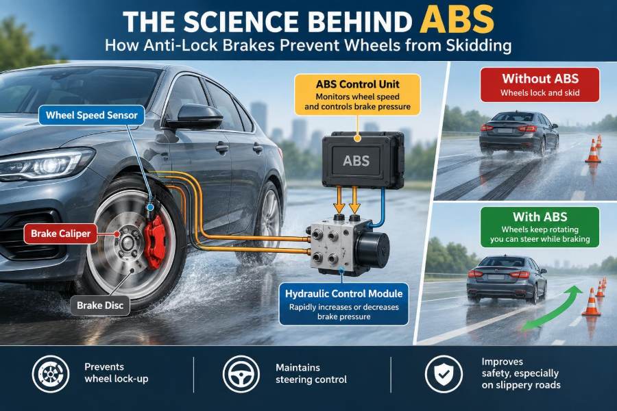

A driver sees traffic slowing suddenly on a wet road and presses the brake pedal hard. In a vehicle without anti-lock braking, the wheels may stop rotating while the car is still moving. The tyres then slide across the surface, and steering becomes far less effective at exactly the moment it is needed most.
Most drivers recognise ABS from the brief vibration or pulsing felt through the brake pedal during a hard stop. That sensation can seem alarming, yet it is evidence of a control system working at high speed to keep the tyres close to their best available grip.
Anti-lock braking systems are now familiar equipment, but their operation connects tyre physics, sensors, hydraulic engineering, electronics, and vehicle dynamics. Understanding those connections helps drivers use ABS correctly and helps engineering students see why a seemingly simple braking task requires rapid feedback control.
The central goal is not merely to stop a wheel from locking. It is to preserve a small but crucial amount of tyre rotation so the vehicle can continue to generate braking force and respond to steering input.
🚘 The problem ABS was designed to solve
During heavy braking, the braking torque applied at each wheel can exceed the tyre-road force available to slow that wheel. If this happens, the wheel decelerates to zero rotational speed and locks while the vehicle body continues moving forward.
A locked tyre slides rather than rolls. On many ordinary paved surfaces, a sliding tyre produces less usable longitudinal grip than a tyre operating near its peak braking condition. More importantly, the contact patch has little remaining capacity to create side force for steering.
ABS continuously reduces and reapplies brake pressure before sustained lock-up develops. It gives the driver a better chance to slow down while retaining directional control.
🛞 Rolling, slipping, and sliding
A rolling wheel has a contact patch that is briefly stationary relative to the road at the instant it touches the ground. Under braking, the tread deforms and the wheel rotates slightly more slowly than its free-rolling speed. This controlled difference is called slip.
Some slip is necessary to create braking force. The challenge begins when slip rises too far: the wheel approaches lock, the tyre enters a slide, and grip usually falls away.
Think of pushing a heavy box. It often takes more force to start it sliding than to keep it moving. Tyres have their own complex friction behaviour, but the useful lesson is that the transition from rolling contact to full sliding changes the forces available to the vehicle.
📐 Understanding wheel slip ratio
Engineers commonly describe braking slip using the difference between vehicle speed and wheel circumferential speed. A freely rolling wheel has very low braking slip, while a locked wheel has 100 percent braking slip because its rotational speed is zero.
Maximum tyre braking force often occurs at an intermediate slip level rather than at zero slip or full lock. The exact region varies with tyre construction, tread, inflation, load, road texture, water, temperature, and surface contamination.
ABS does not measure tyre friction directly in a simple universal way. Instead, it uses wheel-speed behaviour and control logic to keep each wheel near a productive operating region without allowing it to remain locked.
🧲 Why a locked wheel cannot steer well
A tyre has a limited friction capability at its contact patch. Braking uses part of that capability in the forward-rearward direction, while cornering uses it sideways. A tyre near full lock has used its available interaction with the road in an uncontrolled slide, leaving very little lateral authority.
This is why a driver can turn the steering wheel during a locked-wheel skid yet see little change in direction. The front tyres are no longer rolling and building useful side force.
By allowing the wheels to rotate, ABS helps preserve the conditions needed for evasive steering. It cannot create grip where none exists, but it can help the driver make better use of the grip that remains.
📈 The tyre friction curve
A simplified tyre friction curve rises as braking slip increases, reaches a peak, and then commonly drops or levels off as the tyre approaches a full slide. Real curves are not fixed: a dry, rough road behaves differently from wet asphalt, snow, loose gravel, or ice.
This curve explains a key ABS principle: maximum pedal force does not automatically mean maximum tyre force. Brake pressure has to be managed so the tyre stays near a high-grip region.
Control systems must also accept uncertainty. Because the surface can change from one moment to the next, ABS responds to detected wheel deceleration rather than assuming a single ideal slip value for every road.
⚖️ Weight transfer during braking
When a vehicle decelerates, its centre of mass tends to continue moving forward. The suspension transfers more vertical load to the front tyres and reduces load on the rear tyres. This is called longitudinal load transfer.
Front brakes therefore usually perform a larger share of braking in a hard stop, while rear wheels can become easier to lock. The amount of transfer depends on deceleration, wheelbase, centre-of-mass height, and vehicle mass distribution.
ABS controls individual wheels or wheel groups because their available grip may differ. A lightly loaded rear wheel on a rough patch can be close to lock even while the front tyres still have substantial grip.
🧱 Brake bias before electronic control
Conventional brake systems use hydraulic proportioning, brake sizing, and mechanical design to distribute force between front and rear axles. These features aim to prevent rear-wheel lock before front-wheel lock over typical loading conditions.
However, a fixed or mechanically varying bias cannot perfectly account for every passenger load, downhill grade, split-friction road, tyre condition, or rapid manoeuvre. It is necessarily a compromise.
ABS adds active adjustment. It does not replace sound base brake design; it builds on it by changing pressure at the wheel when measured behaviour indicates imminent lock-up.
🔍 The core parts of an ABS
An anti-lock braking system consists of several closely coordinated parts. The architecture differs among vehicles, but the functional roles are consistent.
- Wheel-speed sensors measure wheel rotation.
- An electronic control unit interprets sensor signals and makes control decisions.
- A hydraulic modulator changes brake-fluid pressure using valves and, in many systems, a pump.
- Brake calipers or wheel cylinders convert fluid pressure into clamping force at the wheel.
- Warning circuitry alerts the driver when a relevant fault is detected.
The system acts as a closed loop: measure, compare, adjust, and measure again.
📡 Wheel-speed sensors and tone rings
Each monitored wheel has a speed sensor and a rotating target, often called a tone ring or encoder ring. Earlier arrangements commonly used toothed rings, while many modern systems use magnetic encoder rings integrated with a wheel bearing or hub assembly.
As the target passes the sensor, it creates an electrical signal from which the control unit calculates wheel speed. The controller looks not only at speed, but also at how quickly that speed changes.
A corroded tone ring, damaged encoder, loose connector, or incorrect wheel bearing can corrupt this signal. Since ABS decisions depend on accurate wheel motion information, sensor faults are a major diagnostic concern.
🧠 What the ABS control unit calculates
The ABS electronic control unit compares the speed of one wheel with estimated vehicle speed and with the behaviour of other wheels. It watches for patterns associated with an impending lock, such as unusually rapid wheel deceleration during braking.
Vehicle speed is an estimate, especially when every wheel is changing speed. The controller may infer it from the fastest plausible wheel speed, filtered signals, and learned vehicle behaviour. Its algorithms are designed to remain useful despite noise, road bumps, and changing tyre radius.
Modern control logic is proprietary and vehicle-specific, but the engineering purpose is clear: identify excessive slip quickly enough to intervene before prolonged sliding occurs.
💧 The hydraulic modulator’s three actions
Once the controller detects an impending lock, the hydraulic modulator can alter pressure to the affected brake circuit. A simplified cycle has three actions: increase pressure, hold pressure, and decrease pressure.
During pressure reduction, valves isolate or release pressure from the caliper or wheel cylinder so braking torque falls and the wheel can recover speed. A pump may return fluid so the system can continue operating during repeated cycles.
The cycle repeats rapidly while the driver maintains brake-pedal force. The driver does not need to release and reapply the brakes manually; that is precisely the repetitive task ABS automates.
🔁 Why the brake pedal pulses
Valve switching and pump operation create pressure changes that can be transmitted back through the brake pedal. Drivers may feel a pulse, vibration, or brief movement, and may hear clicking or buzzing from the modulator.
These sensations are generally normal when ABS activates during a genuine low-grip or emergency braking event. The correct response is usually to maintain firm, steady pedal pressure and look where the vehicle needs to go.
Suddenly lifting off the pedal because of the pulsation can reduce braking effort. In contrast, a warning light or abnormal pedal behaviour during ordinary driving deserves inspection rather than assumption.
⏱️ Why ABS responds faster than a driver can modulate
Before ABS, skilled drivers were taught cadence braking: applying and releasing brake pressure repeatedly to avoid a long skid. That technique asks a person to sense a lock-up and make many rapid corrections while also steering and judging hazards.
An electronic system observes wheel-speed signals continuously and can command individual hydraulic changes far more consistently than manual pedal pumping. It also distinguishes wheel behaviour, allowing one wheel to receive a pressure reduction while another continues braking strongly.
This advantage is most valuable when the surface is uneven, grip changes unexpectedly, or the driver must steer around an obstacle under heavy braking.
🛣️ What happens on dry pavement
On dry, uniform pavement with good tyres, a vehicle may stop very effectively even before ABS needs to intervene. If the driver brakes near the grip limit, however, ABS can prevent a wheel from developing a sustained lock as load shifts and tyre forces change.
Activation on dry pavement can occur in a severe stop, on bumps that briefly unload a wheel, or where local surface grip differs. The system may cycle only at one wheel, so the event is not always felt as dramatic pedal pulsation.
Good dry-road stopping remains dependent on tyre condition, brake condition, speed, and following distance. ABS is not a substitute for leaving enough space to react.
🌧️ Wet roads and changing grip
Water lowers available grip by separating parts of the tyre from the road surface and reducing direct rubber-road interaction. At higher speed or deeper water, a tyre can also hydroplane, riding partly on a water film.
ABS is particularly useful when a wet road contains patches of different grip, such as painted markings, metal covers, pooled water, or polished intersections. A wheel reaching a slippery patch can decelerate sharply, prompting pressure reduction before it remains locked.
ABS cannot overcome hydroplaning. Reducing speed before standing water, maintaining legal tread depth, and using suitable tyres remain essential.
❄️ Snow, ice, gravel, and loose surfaces
ABS preserves steerability on many low-grip surfaces, but stopping distance does not always become shorter. On loose gravel, deep snow, or some unpaved surfaces, a locked wheel can build a wedge of material ahead of the tyre that contributes to deceleration.
ABS avoids relying on that effect because a locked wheel sacrifices much of its directional control. The system is generally designed around controlled vehicle behaviour, not simply the shortest possible distance in every unusual surface condition.
On ice, available friction can be extremely low regardless of electronics. Drivers should expect much longer stopping distances and make gentle, early inputs.
↔️ Split-μ braking and directional stability
A split-μ surface has different friction levels on the left and right sides of the vehicle. For example, the left tyres might be on wet leaves while the right tyres remain on dry asphalt. The symbol μ is commonly used for coefficient of friction.
Without wheel-specific control, the low-grip side may lock while the high-grip side continues producing strong braking force. This unequal force creates a yaw moment that tries to rotate the vehicle.
ABS modulates the wheels according to their individual behaviour, improving stability and helping the driver maintain the intended path. It cannot eliminate all pulling forces, so steady steering and a clear escape path still matter.
🚙 ABS channel layouts
ABS systems are often described by the number of sensor inputs and independently controlled hydraulic channels. More individual control generally gives the system a better ability to manage unequal wheel conditions.
| Layout concept | Typical control approach | Practical consequence |
|---|---|---|
| Four-channel, four-sensor | Each wheel monitored and controlled separately | Strong individual wheel control, common in modern passenger vehicles |
| Three-channel arrangements | Front wheels separate; rear axle may share control | Used in some older designs and certain vehicle layouts |
| Rear-wheel-only arrangements | Primarily controls rear-wheel lock | Found in some older light trucks; offers less complete control |
The layout alone does not describe total performance. Tyres, calibration, chassis design, and the condition of the braking system all influence real behaviour.
🧭 ABS, traction control, and stability control
ABS manages wheel slip primarily during braking. Traction control addresses excessive driven-wheel slip during acceleration, often by reducing engine torque, applying a brake at a spinning wheel, or both.
Electronic stability control uses wheel speeds along with sensors such as steering-angle, yaw-rate, and lateral-acceleration sensors. It can brake selected wheels to help correct understeer or oversteer when the vehicle is not following the driver’s intended path.
These systems share hardware and principles, but they solve different problems. A fault affecting wheel-speed data can therefore affect more than one dashboard warning function.
⚙️ Electronic brake-force distribution
Electronic brake-force distribution, often called EBD, uses ABS hardware to manage front-to-rear brake-force balance during normal and heavy braking. It can respond to changing vehicle load more flexibly than a purely mechanical proportioning valve.
For instance, a heavily loaded rear axle can accept more rear braking force than a lightly loaded one before lock-up becomes likely. EBD can use available rear tyre grip without waiting for a full ABS event.
Its operation is usually unobtrusive. The driver may never notice it, yet it illustrates how anti-lock hardware has become a foundation for broader brake control.
🦶 How to brake correctly in an ABS-equipped vehicle
In an emergency, press the brake pedal firmly and keep steady pressure on it. If there is space and the vehicle remains responsive, steer toward the available safe path rather than staring at the obstacle.
- Keep both hands positioned to make controlled steering inputs.
- Do not pump the brakes when ABS is active.
- Do not assume ABS will compensate for excessive entry speed into a corner.
- Maintain tyres, because the system can only work with the grip the tyres can generate.
Driver training can refine technique, especially for commercial vehicles or winter conditions, but the basic principle is firm braking and controlled steering.
🚫 Common driver mistakes during ABS activation
One common mistake is releasing the pedal at the first vibration. Another is pumping the pedal, which can interfere with the driver’s ability to maintain maximum commanded braking pressure.
Some drivers also steer abruptly back and forth. ABS may preserve steering capability, but sudden large steering angles can overload the front tyres and destabilise the vehicle. Look toward the intended route and make one measured steering action where possible.
Finally, do not interpret ABS as permission to follow closely. The system helps manage an emergency; safe speed and space reduce the chance of needing one.
🔧 Tyres remain the first link in the chain
ABS controls brake pressure, not the road surface. A worn, underinflated, damaged, or unsuitable tyre has less ability to transmit braking and cornering forces, particularly in wet weather.
Tread depth helps channels move water away from the contact region, while correct inflation helps maintain the intended contact patch and carcass behaviour. Uneven wear can also make wheel behaviour less predictable during a hard stop.
When evaluating braking performance, start with tyres before blaming electronics. The most sophisticated controller cannot manufacture friction from a compromised contact patch.
🛠️ Brake condition and hydraulic health
ABS does not remove the need for conventional brake maintenance. Worn pads, damaged discs, seized caliper slides, leaking fluid, contaminated brake fluid, and corroded lines can reduce braking performance or create uneven forces.
A hydraulic fault may also affect the modulator’s ability to control pressure correctly. Service procedures for ABS-equipped systems can differ from older systems because some designs require scan-tool commands to cycle valves or pumps during bleeding.
Use the manufacturer’s service information and specified brake fluid. Brake work is safety-critical, so uncertain diagnosis or repair should be handled by a qualified technician.
⚠️ What an ABS warning light means
An illuminated ABS warning light usually indicates that the system has detected a fault and may have disabled anti-lock operation. In many vehicles, the base hydraulic braking system still operates, but the driver may no longer have ABS, and related functions such as traction or stability control may also be limited.
The exact meaning depends on the vehicle and warning combination. A red brake-system warning can indicate a more urgent issue than an amber ABS lamp and should not be ignored.
Check the owner’s manual, avoid assuming the vehicle is fully protected, and arrange diagnosis promptly. Reading fault codes is only the beginning; wiring, sensors, mechanical components, and signal quality may need testing.
🧪 Diagnosing sensor-related ABS faults
A diagnostic scan tool can identify stored fault information, but a code naming a wheel does not automatically prove that the sensor itself has failed. The fault may arise from a damaged harness, connector corrosion, excessive wheel-bearing play, a contaminated encoder ring, or an implausible signal.
Technicians often compare live wheel-speed data during a careful road test or wheel rotation test, then inspect the physical installation. An intermittent dropout at low speed can be especially revealing.
Replacing parts without confirming the cause can be expensive and ineffective. Good diagnosis follows the signal path from the rotating target to the control unit.
🏁 ABS in motorcycles, trucks, and other vehicles
Motorcycles use ABS too, but calibration must account for two wheels, rapid load transfer, lean angle in some advanced systems, and the consequences of a front-wheel lock. Riders still need smooth braking technique and appropriate following distance.
Heavy trucks and trailers have pneumatic braking systems and different axle loads, yet they face the same fundamental problem: a locked wheel reduces tyre control. Their ABS systems modulate air pressure rather than brake fluid.
Off-road vehicles may offer selectable modes that permit more wheel slip on loose terrain. Such modes reflect a purposeful trade-off between directional control, surface behaviour, and traction needs; drivers should follow the vehicle manufacturer’s guidance.
📚 A control-systems view of ABS
ABS is a practical example of feedback control. The driver requests deceleration with the pedal, sensors provide feedback on wheel behaviour, the controller compares that behaviour with acceptable limits, and actuators modify hydraulic pressure.
There is a delay between a valve command and changed tyre force, and the road surface itself is uncertain. For that reason, ABS calibration must avoid both slow reaction and excessive oscillation. A system that releases pressure too late permits lock; one that releases too aggressively gives away braking force.
This makes ABS a useful engineering case study in sensors, estimation, nonlinear tyre behaviour, hydraulic actuation, and robust real-world control.
🧩 The core takeaway: controlled slip preserves control
The defining idea behind ABS is simple but powerful: tyres brake best when they are close to the limit of adhesion without remaining locked. The system monitors wheel rotation and modulates brake pressure to manage that narrow operating zone.
Its benefits are most meaningful when a driver must brake hard and still steer, particularly when grip varies from wheel to wheel. Yet ABS has firm limits set by road friction, tyre condition, speed, vehicle condition, and driver decisions.
Understanding those limits leads to the right mindset: use firm, steady braking in an emergency, maintain the vehicle properly, and create safety margins before a crisis demands the system’s help.
ABS does not defeat physics; it helps each tyre use available grip without giving up the ability to steer. That combination of controlled slip, sound maintenance, and sensible driving is what turns a sophisticated brake system into real safety value. 🚗🛞⚙️