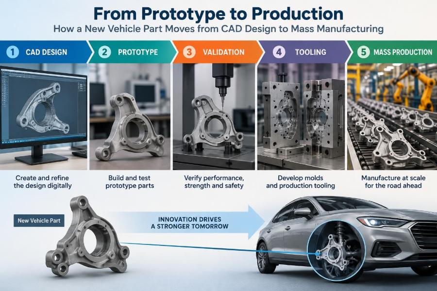

A door handle that feels solid, a brake pedal that returns predictably, and a dashboard vent that fits without a visible gap all look like small details to a driver. Behind each one is a long engineering journey that began long before the first production vehicle reached a road.
For students, the phrase “design a part in CAD” can make vehicle development seem mostly digital. For working engineers, the reality is familiar: a clean model is only the starting point. The part must be made repeatedly, measured reliably, assembled quickly, survive real service, and remain affordable.
Consider a hypothetical aluminium suspension bracket. It may appear to be a simple shaped component, but it must carry fluctuating loads, clear nearby parts, accept fasteners, resist corrosion, and be produced with stable dimensions across thousands of units.
That is why the path from computer-aided design to mass manufacturing is not a straight line. It is a controlled sequence of decisions, tests, feedback loops, and trade-offs that turns engineering intent into a dependable physical product.
🧭 The Journey Is a Product Development System
A vehicle part moves through connected stages rather than isolated departments. Product planning defines the need; design creates the concept; analysis and testing reduce risk; manufacturing engineering defines the process; quality systems verify consistency.
Each stage changes the definition of “good.” Early on, a good concept satisfies a function. Later, it must satisfy strength, packaging, cost, assembly time, serviceability, legal requirements where applicable, and process capability.
📋 Starting With a Clear Engineering Requirement
The process begins with requirements, often captured in a design specification. This document converts a broad request—such as “reduce cabin noise” or “support the front bumper”—into measurable targets and constraints.
Typical requirements include load cases, allowable movement, operating temperature, target mass, lifetime, interfaces, appearance, materials restrictions, and manufacturing volume. Vague requirements create expensive redesign because different teams will make different assumptions.
- A mounting bracket may need defined stiffness under load.
- A trim part may need a controlled colour, texture, and gap to adjacent panels.
- An electrical housing may need sealing, connector retention, and heat resistance.
🚘 Understanding the Part’s Real Job
Function must be understood in context. A plastic clip does not merely “hold a panel”; it may control panel location, prevent rattle, tolerate repeated removal, and keep its retention force after heat and humidity exposure.
Engineers therefore map load paths, user interactions, environmental exposure, and failure consequences. A cosmetic cover and a steering component can both be injection-moulded, but their safety implications and validation depth are very different.
🧩 Packaging and Interface Management
Every part occupies a finite three-dimensional space called its package. It must coexist with surrounding components, moving mechanisms, wiring, tools used in assembly, and sometimes the human hand during service.
Interfaces are especially critical: bolt patterns, clip locations, connector geometry, sealing surfaces, datum features, and mating clearances. A part can meet all its own dimensions yet still fail if its interface assumptions do not match those of the adjacent assembly.
💻 Building the Initial CAD Concept
Computer-aided design, or CAD, lets engineers create parametric geometry: dimensions, relationships, and features that can be changed systematically. A mounting hole can remain centred on a boss, for example, even when the boss position changes.
The first model commonly prioritizes function and package space. It may include simplified surrounding geometry, known as a digital mock-up, to expose clashes before physical material is committed.
📐 Choosing Datums Before Chasing Dimensions
A datum is a theoretically exact reference used to locate or orient a part for manufacture and inspection. Good datum strategy reflects how the component is assembled and how its critical function is measured.
For a brake caliper bracket, functional mounting faces and bores are stronger datum candidates than an arbitrary outside edge. Poor datum selection can produce parts that pass individual checks but misalign when bolted to the vehicle.
🧱 Selecting Material and Manufacturing Route Together
Material selection cannot be separated from process selection. A geometry suited to die casting may not be suitable for forging; a polymer that moulds well may lose stiffness near an under-bonnet heat source.
Engineers compare mechanical properties, corrosion behaviour, density, temperature capability, joining method, surface finish, recyclability, supply availability, and cost. The relevant property is not simply the highest strength, but the property that remains dependable in service.
| Part need | Possible route | Key design consideration |
|---|---|---|
| Thin, high-volume interior trim | Injection moulding | Wall thickness, draft, sink marks, texture |
| High-load steel arm | Stamping or forging | Grain flow, forming limits, weld access |
| Complex aluminium housing | Die casting | Draft, porosity risk, machining allowance |
| Low-volume complex duct | Additive manufacture or formed fabrication | Build direction or joining strategy |
🏭 Designing for Manufacture and Assembly
Design for manufacture and assembly, often abbreviated DFMA, asks a direct question: can this part be made and fitted repeatedly with reasonable cost and variation? It brings manufacturing knowledge into design early, when changes are cheaper.
Examples include adding draft angles so a moulded part can be ejected, avoiding inaccessible welds, standardizing fasteners, and providing features that make incorrect orientation difficult. A part that is elegant in CAD but awkward to fixture is not production-ready.
↔️ Managing Tolerances Instead of Demanding Perfection
No process produces identical parts. Tolerances define the acceptable variation in size, shape, position, and surface condition while preserving the intended function.
Tighter tolerances can improve fit in some cases, but they often raise tooling, machining, inspection, and scrap costs. The goal is not maximum precision everywhere; it is appropriate precision at function-critical features.
📊 Using GD&T to Communicate Functional Intent
Geometric dimensioning and tolerancing, or GD&T, controls geometric conditions such as position, flatness, perpendicularity, and profile. It communicates more than a collection of plus-or-minus dimensions.
For example, a positional tolerance on a hole pattern can state how holes must relate to defined datums. This helps suppliers, manufacturing engineers, and inspectors assess the same functional requirement rather than interpreting a drawing differently.
🧮 Simulating Loads Before Making Hardware
Computer-aided engineering, or CAE, uses numerical models to estimate behaviour before prototypes are built. Finite element analysis is widely used to predict stress, deformation, vibration modes, and fatigue-sensitive regions.
A simulation is only as credible as its assumptions. Boundary conditions, material data, mesh quality, contact definitions, and load cases all matter. CAE narrows the design space; it does not eliminate the need for physical testing.
🌡️ Accounting for Heat, Vibration, and Ageing
Vehicles operate through temperature changes, vibration, moisture, road salt, dust, fluids, sunlight, and repeated use. These conditions can alter material stiffness, create corrosion, loosen joints, or accelerate wear.
A cooling-system connector might be dimensionally correct at room temperature but leak after thermal cycling. A wiring clip might retain a cable when new but fret against a body panel after long vibration exposure. Environmental design is therefore part of basic function, not an afterthought.
⚠️ Anticipating Failure Modes Early
Failure mode thinking asks how a part could fail, why that failure might happen, how severe its effect would be, and whether the issue can be detected. Teams often document this through structured risk-analysis methods such as design FMEA.
Potential failures may include cracking, leakage, loosening, excessive noise, wrong assembly orientation, electrical shorting, or loss of corrosion protection. The useful outcome is action: revise geometry, add a control, improve detection, or change the process.
🖨️ Creating Early Physical Prototypes
Prototype parts turn digital assumptions into tangible evidence. Depending on the purpose, teams may use 3D printing, CNC machining, laser-cut sheet, soft tools, or hand-built assemblies.
A rapid prototype can confirm hand clearance, ergonomics, routing, and visual fit. It may not represent final strength, grain structure, surface finish, or production variation, so conclusions must be limited to what that prototype can truly demonstrate.
🔍 Verifying Form, Fit, and Function
Prototype evaluation normally progresses from form to fit to function. Form checks geometry and appearance; fit checks interfaces and installation; function checks whether the component performs under expected conditions.
For a hypothetical centre-console latch, a team may first confirm panel alignment, then check that it installs with the intended tool, and finally measure opening force through repeated cycles. Separating these questions prevents one successful observation from being treated as total validation.
🧪 Validating the Design Against Real Use
Validation tests assess whether the design meets its requirements under relevant service conditions. The plan may include static load, fatigue cycling, temperature exposure, chemical resistance, corrosion exposure, water ingress, vibration, and abuse cases.
Test conditions must represent the part’s intended environment and failure consequences. A safety-related component usually requires a more rigorous evidence trail than a non-structural decorative piece, though both still need appropriate quality control.
🔁 Learning From Test Failures
A failed test is valuable when it reveals a mechanism. Simply increasing material thickness may hide a symptom while increasing mass, cost, or a new manufacturing problem.
Teams investigate crack origin, load direction, assembly condition, material state, and test setup. A failure near a sharp corner may suggest stress concentration; a leak near a joint may point to surface finish, clamping force, or tolerance stack-up.
🛠️ Developing Production Tooling
Once the design and manufacturing route mature, suppliers develop production tooling: stamping dies, injection moulds, casting dies, forging tools, fixtures, gauges, and machining workholding. These tools control both shape and repeatability.
Tooling represents a major commitment because late geometry changes can require rework and delay. Design release should therefore be based on sufficient evidence, while recognizing that controlled improvements may still emerge during production trials.
🏗️ Planning the Manufacturing Process
Manufacturing engineers define the route from raw material to finished part. A process plan identifies operations, sequence, equipment, parameters, inspection points, handling methods, and traceability needs.
For a machined casting, the route might include casting, trimming, heat treatment where specified, machining, washing, leak testing, coating, final inspection, and packing. The order matters because one operation can establish datums or create conditions needed by the next.
🤖 Designing the Assembly Station
Production design extends beyond the component to the station where it is installed. Engineers consider reach, part presentation, tool access, torque reaction, cycle time, and the likelihood of human error.
Poka-yoke, meaning mistake-proofing, is especially useful. A connector may be keyed so it cannot be inserted incorrectly, or a fixture may allow a bracket to sit in only one orientation. Such features prevent defects rather than relying solely on final inspection.
📏 Building Measurement Into the Process
Inspection equipment must measure what matters and do so consistently. Coordinate measuring machines, go/no-go gauges, vision systems, leak testers, torque monitoring, and functional testers are selected according to the feature and production rate.
Measurement-system analysis checks whether a gauge can distinguish real part variation from its own repeatability and operator variation. Measuring an important dimension poorly creates false confidence and can lead to incorrect production decisions.
📈 Proving Process Capability
A capable process produces output that stays within specification with practical margin, not merely a few accepted samples. Trial builds help reveal how tool temperature, machine settings, material batches, operator handling, and equipment wear affect the result.
Process capability is assessed using production data and the agreed tolerance limits. Capability results should be interpreted with engineering context: a stable process centred near a limit may still need adjustment, even if early parts appear acceptable.
🚦 Running Pilot Builds and Pre-Production Trials
Pilot builds use production-intent parts, tools, equipment, and methods as far as practical. They expose issues that laboratory prototypes often cannot: part feeding problems, cycle-time losses, mixed components, unstable fastening, or packaging damage.
These builds also test the supply chain. A technically sound part is not ready for volume if material delivery, supplier capacity, labelling, or incoming inspection cannot support the planned build rhythm.
🔗 Managing Suppliers and the Supply Chain
Modern vehicle parts are often developed across several organizations. The vehicle manufacturer, tier supplier, sub-supplier, toolmaker, material producer, and test laboratory need controlled communication of drawings, revisions, specifications, and changes.
Supplier selection involves more than quoted price. Relevant considerations include technical competence, manufacturing maturity, quality history, capacity, logistics, material traceability, and the ability to respond when a process drifts.
📦 Protecting the Part After It Is Made
Manufacturing quality can be lost during storage and transport. Machined sealing faces can be scratched, coated parts can rub together, clips can deform in bulk containers, and moisture-sensitive electronics can require controlled handling.
Packaging is therefore an engineering element. Good packaging protects critical surfaces, supports traceability, suits handling equipment, and avoids adding unnecessary material or labour.
✅ Approving the Part for Series Production
Before full-rate production, organizations compile evidence that the product and process meet agreed requirements. The exact approval method varies by company and supply-chain arrangement, but it commonly includes drawings, material evidence, test results, dimensional reports, process documentation, and sample parts.
Approval is not a declaration that nothing can ever go wrong. It is a decision that the design and process have enough demonstrated control to enter series production under defined conditions.
🔄 Controlling Engineering Changes
Changes continue after release. A supplier may replace a machine, a material source may change, a tool may be repaired, or a field issue may require a redesigned feature. Even a small change can affect fit, durability, appearance, or certification evidence.
Effective change control records what changed, why it changed, which parts are affected, what validation is needed, and how old and new stock will be separated. Uncontrolled changes are a common route to confusing, intermittent quality problems.
🕵️ Monitoring Quality During Mass Manufacturing
Series production relies on layered controls: incoming material checks, in-process monitoring, automated error detection, sampling plans, final audits, and traceability. The best systems react to trends before they become widespread nonconformities.
For example, rising insertion force on a press-fit operation may indicate tool wear or material variation. Detecting that shift early is more effective than waiting for assembled products to fail a final functional check.
🛣️ Using Field Feedback to Improve the Next Revision
Vehicles in customer use reveal combinations of climate, road condition, maintenance practice, and ageing that development tests may not reproduce perfectly. Warranty information, service reports, returned parts, and production feedback can identify patterns worth investigating.
Field evidence requires careful interpretation. A reported failure may arise from misuse, installation, a neighbouring system, or the part itself. Root-cause work should connect observations to physical evidence before a design or process change is made.
🎯 What Students and Engineers Should Remember
The central lesson is that a vehicle part is not finished when its CAD model looks correct. It is finished only when the design intent can be translated into a repeatable manufacturing process and verified in the conditions the part will face.
Strong development teams connect disciplines early: design engineers understand process limits, manufacturing engineers understand functional intent, quality engineers understand risk, and suppliers contribute practical knowledge. Production readiness is the meeting point of function, manufacturability, validation, and control.
A successful production part is the result of many connected decisions: clear requirements, functional geometry, realistic tolerances, meaningful testing, capable tooling, disciplined quality control, and continuous learning after launch. That systems view is what turns a promising prototype into a vehicle component drivers can depend on every day. 🚗⚙️🔧